
LiftMaster Liftmaster LA400 - 1 - Kit
LiftMaster LA400 Residential DC Linear Gate Operator User Manual
Model: Liftmaster LA400 - 1 - Kit | Brand: LiftMaster
Product Overview
The LiftMaster LA400 is a robust 24VDC linear gate operator designed for residential swing gate applications. It features a powerful motor that delivers exceptional starting torque and incorporates soft start/stop functionality, which extends the lifespan of both the gate and the operator while ensuring reliable performance. This operator is capable of handling gates up to 16 feet long and weighing up to 550 pounds.
As a low-voltage system, it simplifies installation by not requiring a licensed electrician and is compatible with low-voltage wiring. The battery-run system provides continuous operation during power outages, with an optional solar charging capability for enhanced energy independence. It includes an easy-to-set electronic limit system, user-friendly inputs for various sensing and control devices, a built-in adjustable timer to close, and supports primary/secondary gate operation. LED diagnostics are integrated to assist with quick and efficient installation and troubleshooting.
Key Features
- Requires LA400-CONT Control Box (Not Included)
- On-Board Radio Receiver for remote control integration
- Battery-Run DC System for uninterrupted operation
- Soft Start/Stop functionality for extended gate and operator life
- Inherent Obstruction Sensing for enhanced safety
- Simple-to-set electronic limit system
- Built-in fully adjustable timer to close
- Supports primary/secondary gate operation
- LED diagnostics for simplified installation and troubleshooting
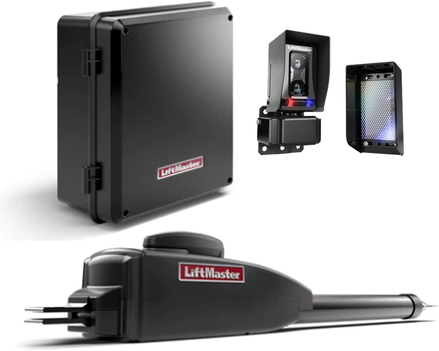
Figure 1: Main components of the LiftMaster LA400 system, including the control box, the LMRRUL Monitored Retroreflective Photoelectric Sensor, and the LA400DC Primary 24 VDC Actuator Arm.
Setup and Installation
Installation of the LiftMaster LA400 gate operator requires careful attention to detail and adherence to safety guidelines. While the low-voltage design simplifies some aspects, it is highly recommended that installation be performed by a qualified professional to ensure proper functionality, safety, and compliance with local codes.
Components Included
- LMRRUL Monitored Retroreflective Photoelectric Sensor
- LA400DC Primary 24 VDC Actuator Arm (for single swing gate applications)
- Note: The LA400-CONT Control Box is required but not included with this specific kit.
Pre-Installation Checklist
- Verify gate dimensions and weight are within operator specifications (up to 16 ft long, up to 550 lbs).
- Ensure a suitable mounting surface for the actuator arm and control box.
- Confirm availability of a power source for the control box (24VDC).
- Plan for wire runs for power, safety devices, and control devices.
- Acquire the necessary LA400-CONT Control Box if not already possessed.
Installation Steps (General Overview)
- Mount the Actuator Arm: Securely attach the LA400DC actuator arm to the gate and post according to the detailed instructions provided in the full installation manual. Proper alignment is critical for smooth operation.
- Install the Control Box: Mount the LA400-CONT Control Box in a protected, accessible location near the gate.
- Wire Components: Connect the actuator arm, photoelectric sensor, and any other desired control or safety devices (e.g., loops) to the control box. Follow the wiring diagrams precisely.
- Connect Power: Connect the 24VDC power supply to the control box. Ensure all connections are secure and insulated.
- Set Electronic Limits: Utilize the simple electronic limit system to program the open and close positions of the gate. This involves manually moving the gate to the desired positions and saving them via the control board.
- Test Obstruction Sensing: Verify the inherent obstruction sensing feature by placing an object (e.g., a cardboard box) in the gate's path during operation. The gate should reverse upon contact.
- Adjust Timer to Close: If desired, set the built-in adjustable timer for automatic gate closure after a set period.
- Program Remotes: Program any remote controls or access devices to the on-board radio receiver.
- Final Testing: Conduct multiple full cycles of gate operation to ensure all functions are working correctly and safely.
Operation
The LiftMaster LA400 gate operator is designed for user-friendly operation once properly installed and configured. It offers reliable and secure access control for your property.
Basic Operation
To open or close the gate, activate the system using a programmed remote control, keypad, or other connected access device. The operator will initiate a soft start, gradually increasing speed, and then perform a soft stop as it reaches its programmed open or close limit. This controlled movement reduces wear and tear on the gate and the operator.
Timer to Close
The integrated timer to close feature allows the gate to automatically close after a user-defined period following an opening cycle. This feature can be adjusted or disabled via the control box settings. Ensure the path is clear before enabling this function.
Primary/Secondary Operation
For dual gate installations, the LA400 supports primary/secondary operation, allowing two operators to work in synchronized motion. This configuration requires specific wiring and programming as detailed in the comprehensive installation manual.
Maintenance
Regular maintenance is crucial to ensure the longevity and optimal performance of your LiftMaster LA400 gate operator. Performing routine checks can prevent potential issues and ensure safe operation.
Routine Checks
- Monthly: Inspect the gate for any signs of wear, damage, or obstruction. Ensure the gate moves freely without the operator.
- Quarterly: Check all mounting hardware for tightness. Verify that the actuator arm is securely attached to both the gate and the post.
- Semi-Annually: Test the inherent obstruction sensing feature by placing a soft object (e.g., a cardboard box) in the gate's path during both opening and closing cycles. The gate should stop and reverse.
- Annually: Inspect all wiring for signs of wear, fraying, or damage. Ensure connections are clean and secure.
Battery System
The LA400 operates on a battery-run DC system, providing backup power during outages. While the system is designed to maintain the battery, regular checks of battery health are recommended, especially if the gate is frequently used during power failures or if the solar option is not utilized. Consult the LA400-CONT Control Box manual for specific battery maintenance and replacement procedures.
Troubleshooting
This section provides guidance for common issues you might encounter with your LiftMaster LA400 gate operator. For complex problems, it is strongly advised to contact a certified LiftMaster professional.
Common Issues and Solutions
| Problem | Possible Cause | Solution |
|---|---|---|
| Gate does not respond to remote/control. | No power to control box, dead remote battery, remote not programmed, safety device triggered. | Check power supply to control box. Replace remote battery. Reprogram remote. Check photoelectric sensor alignment and clear any obstructions. |
| Gate opens but does not close. | Photoelectric sensor obstruction or misalignment, timer to close disabled or set incorrectly. | Clear path of sensor. Realign sensor. Check timer to close settings in control box. |
| Gate reverses unexpectedly. | Obstruction detected by inherent obstruction sensing, gate binding. | Inspect gate path for obstructions. Check gate hinges and wheels for binding or damage. |
| Gate moves slowly or inconsistently. | Low battery voltage, mechanical friction, motor issue. | Check battery charge. Lubricate gate hinges/wheels. If problem persists, professional service may be required. |
The LA400 control box features LED diagnostics which can provide specific error codes to help identify the root cause of issues. Refer to the LA400-CONT Control Box manual for a complete list of LED diagnostic codes and their meanings.
Technical Specifications
| Specification | Detail |
|---|---|
| Manufacturer | Chamberlain |
| Part Number | LA412-Single 315Pkg |
| Model Number | Liftmaster LA400 - 1 - Kit |
| Power Source | Battery-powered |
| Voltage | 24 Volts DC |
| Max Gate Length | 16 ft |
| Max Gate Weight | 550 lbs |
| Included Components | LMRRUL Monitored Retroreflective Photoelectric Sensor, LA400DC Primary 24 VDC Actuator Arm |
| Control Box Required | LA400-CONT (Not Included) |
Warranty Information
LiftMaster products, including the LA400 gate operator, typically come with a manufacturer's warranty. However, it is important to note that LiftMaster's support policy often directs end-users to professional installers for warranty claims and technical assistance. This is due to the complexity of gate operator systems and safety regulations.
For detailed information regarding the specific terms, conditions, and duration of your warranty, please refer to the warranty documentation included with your LA400-CONT Control Box or contact the authorized LiftMaster dealer from whom you purchased the product. Retain your proof of purchase for any warranty claims.
Customer Support
For technical support, troubleshooting assistance beyond this manual, or professional service, LiftMaster strongly recommends contacting an authorized LiftMaster professional or the installer who performed your gate operator installation. These professionals are trained and equipped to handle complex diagnostics, repairs, and ensure compliance with safety standards.
While direct consumer support from the manufacturer may be limited, authorized dealers and installers are your primary resource for expert assistance with your LiftMaster LA400 system.
Ask a question about this manual
Ask about setup, troubleshooting, compatibility, parts, safety, or missing instructions. Manuals+ will review the question and use this page’s manual context to help answer it.