1. Introduction
The Atlas Sound AA120 is a 120-watt, six-input mixer amplifier designed for commercial audio applications. It features five microphone/line inputs with phantom power, one stereo summing auxiliary input, and versatile output options including 8-ohm, 25V, 70V, and 100V speaker outputs. This manual provides detailed instructions for the proper installation, operation, and maintenance of your AA120 mixer amplifier.
2. Important Safety Instructions
- Read Instructions: Read and understand all safety and operating instructions before using this product.
- Retain Instructions: Keep these instructions for future reference.
- Heed Warnings: Observe all warnings on the product and in the operating instructions.
- Follow Instructions: Follow all operating and usage instructions.
- Water and Moisture: Do not use this apparatus near water.
- Cleaning: Clean only with a dry cloth.
- Ventilation: Do not block any ventilation openings. Install in accordance with the manufacturer's instructions. Ensure adequate airflow around the unit.
- Heat: Do not install near any heat sources such as radiators, heat registers, stoves, or other apparatus (including amplifiers) that produce heat.
- Power Cord Protection: Protect the power cord from being walked on or pinched, particularly at plugs, convenience receptacles, and the point where they exit from the apparatus.
- Servicing: Refer all servicing to qualified service personnel. Servicing is required when the apparatus has been damaged in any way, such as power-supply cord or plug is damaged, liquid has been spilled or objects have fallen into the apparatus, the apparatus has been exposed to rain or moisture, does not operate normally, or has been dropped.
3. Rear Panel Overview
The rear panel of the Atlas Sound AA120 provides all necessary connections for power, inputs, and speaker outputs. Familiarize yourself with these connections before installation.
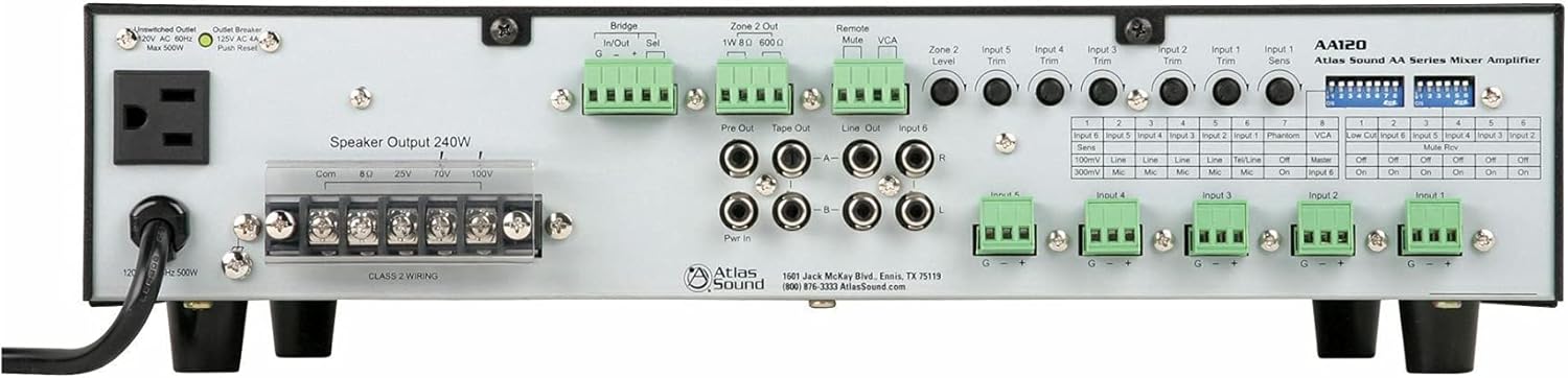
Figure 1: Rear Panel of the Atlas Sound AA120 Mixer Amplifier
Rear Panel Components:
- Unswitched Outlet (120V AC 60Hz, Max 500W): A convenience outlet for powering external equipment.
- Outlet Breaker (125V AC 4A, Push Reset): A resettable circuit breaker for the unswitched outlet. Press to reset if tripped.
- Speaker Output 240W (Com, 8Ω, 25V, 70V, 100V): Terminal block for connecting speakers. Supports common, 8-ohm, 25-volt, 70-volt, and 100-volt speaker systems. Ensure Class 2 wiring is used.
- Bridge In/Out (G, -, +): Terminals for linking multiple amplifiers or integrating with external processing. 'Sel' switch selects bridging mode.
- Zone 2 Out (1W 8Ω, 600Ω): Output for a secondary audio zone, providing 1W at 8 ohms or a 600-ohm line level output.
- Remote Mute: Terminals for connecting an external remote mute switch.
- VCA (Voltage Controlled Amplifier): Terminals for external VCA control.
- Pre Out / Tape Out / Line Out / Input 6 (RCA): RCA jacks for pre-amplifier output, tape recording output, general line output, and stereo auxiliary input (Input 6).
- Pwr In (RCA): RCA jacks for power amplifier input, allowing external pre-amplifiers to drive the AA120's power section.
- Input Trim Controls (Input 1-5, Zone 2 Level): Rotary potentiometers for adjusting the input sensitivity of individual channels and the output level of Zone 2.
- Input 1-5 Terminal Blocks (G, -, +): Balanced input terminals for microphone or line-level sources.
- DIP Switches: A bank of switches for configuring various amplifier functions, including input sensitivity, phantom power, VCA assignment, low-cut filter, and mute reverse.
4. Setup and Installation
4.1 Unpacking
Carefully remove the AA120 from its packaging. Inspect the unit for any signs of damage that may have occurred during transit. Retain the packaging for future transport or storage.
4.2 Placement
Place the amplifier in a location that allows for adequate ventilation. Avoid placing it near heat sources or in direct sunlight. Ensure the unit is on a stable, level surface. Do not obstruct the ventilation openings.
4.3 Power Connection
Connect the supplied AC power cord to the amplifier's power inlet and then to a grounded 120V AC, 60Hz power outlet. The unswitched outlet on the rear panel can provide power to other equipment, up to a maximum of 500W. If this outlet's breaker trips, press the 'Push Reset' button to restore power.
4.4 Speaker Connections
The AA120 supports various speaker configurations. Connect your speakers to the 'Speaker Output 240W' terminal block. Ensure proper polarity and impedance matching.
- 8 Ohm: For direct connection to low-impedance speakers.
- 25V, 70V, 100V: For constant voltage distributed speaker systems. Connect the common (Com) terminal to the negative speaker wire and the appropriate voltage terminal (25V, 70V, or 100V) to the positive speaker wire.
Note: Always ensure the amplifier is powered off before making or changing speaker connections. Use Class 2 wiring for speaker connections.
4.5 Input Connections
The AA120 offers six input channels:
- Inputs 1-5 (Balanced Terminal Blocks): These inputs accept either microphone or line-level signals. Connect balanced audio cables to the G (ground), - (negative), and + (positive) terminals.
- Input 6 (Stereo RCA): This input is designed for stereo line-level sources such as CD players or media players. The stereo signal is summed to mono internally.
4.6 DIP Switch Configuration
The DIP switches on the rear panel allow for fine-tuning of input characteristics and other functions. Refer to the table below for their functions:
| Switch No. | Function | OFF Setting | ON Setting |
|---|---|---|---|
| Input 6 Sens (1) | Input 6 Sensitivity | 100mV Line | 300mV Mic |
| Input 5 Sens (2) | Input 5 Sensitivity | Line | Mic |
| Input 4 Sens (3) | Input 4 Sensitivity | Line | Mic |
| Input 3 Sens (4) | Input 3 Sensitivity | Line | Mic |
| Input 2 Sens (5) | Input 2 Sensitivity | Line | Mic |
| Input 1 Sens (6) | Input 1 Sensitivity | Tel/Line | Mic |
| Phantom (7) | Phantom Power | Off | On |
| VCA (8) | VCA Control Assignment | Master | Input 6 |
| Low Cut (1) | Low Cut Filter | Off | On |
| Input 6 Mute Rev (2) | Input 6 Mute Reverse | Off | On |
| Input 5 Mute Rev (3) | Input 5 Mute Reverse | Off | On |
| Input 4 Mute Rev (4) | Input 4 Mute Reverse | Off | On |
| Input 3 Mute Rev (5) | Input 3 Mute Reverse | Off | On |
| Input 2 Mute Rev (6) | Input 2 Mute Reverse | Off | On |
| Input 1 Mute Rev (7) | Input 1 Mute Reverse | Off | On |
Important: Always power off the amplifier before changing DIP switch settings to prevent potential damage or unexpected behavior.
5. Operating Instructions
5.1 Powering On/Off
To power on the amplifier, ensure all connections are secure, then press the power switch located on the front panel (not visible in rear panel image, but standard). To power off, press the switch again.
5.2 Adjusting Input Levels
Use the 'Input Trim' rotary controls on the rear panel for Inputs 1-5 to adjust the sensitivity of each input channel. This allows you to match the input level of your source device to the amplifier. For Input 6, adjust the source device's output level or use the VCA control if assigned.
5.3 Master Volume Control
The master volume control (typically on the front panel, not shown in rear image) adjusts the overall output level of the amplifier. Start with the master volume at a low setting and gradually increase it to the desired listening level.
5.4 Mute Functions
The AA120 supports remote or VOX (Voice Operated Switch) mute capabilities. The 'Remote Mute' terminals allow for an external switch to mute the audio. The 'Mute Rev' DIP switches (1-7) allow you to reverse the mute logic for individual inputs, useful for paging systems where other audio is muted when a microphone is active.
5.5 Zone 2 Operation
The 'Zone 2 Out' provides a separate audio output. The 'Zone 2 Level' control adjusts the output level for this zone. This can be used for a separate listening area or to feed another amplifier.
5.6 Low Cut Filter
The low-cut filter (6 dB per octave at 400 Hz) can be engaged via the DIP switch. This filter is particularly useful when using paging horns, as it helps to reduce low-frequency content that can cause distortion or reduce intelligibility in such speakers.
6. Maintenance
6.1 Cleaning
To clean the amplifier, disconnect it from the power source. Use a soft, dry cloth to wipe down the exterior. Do not use liquid cleaners or aerosol sprays, as they may damage the finish or internal components.
6.2 Ventilation
Periodically check that the ventilation openings are clear of dust and debris. Proper airflow is crucial for preventing overheating and ensuring the longevity of the amplifier.
7. Troubleshooting
If you encounter issues with your AA120, refer to the following common problems and solutions:
- No Power:
- Ensure the power cord is securely connected to both the amplifier and a working AC outlet.
- Check the main circuit breaker for your building.
- If using the unswitched outlet, check its dedicated 'Outlet Breaker' and press 'Push Reset' if tripped.
- No Sound:
- Verify that speakers are correctly connected to the appropriate output terminals (Com, 8Ω, 25V, 70V, or 100V).
- Check all input connections and ensure source devices are playing audio.
- Ensure input trim controls and master volume are set to audible levels.
- Check DIP switch settings for mute functions; ensure no inputs are inadvertently muted.
- Distorted Sound:
- Reduce input trim levels if the input signal is too strong.
- Ensure speaker impedance matches the amplifier output (e.g., 8Ω speakers to 8Ω terminal).
- Check speaker wiring for shorts or loose connections.
If the problem persists after attempting these troubleshooting steps, contact Atlas Sound customer support for assistance.
8. Specifications
| Feature | Specification |
|---|---|
| Power Output | 120W at 8 ohms, 25V, or 70V |
| Speaker Output Capability | Up to 240W total (Com, 8Ω, 25V, 70V, 100V) |
| Channels | 1 |
| Inputs | 5 Mic/Line inputs (with Phantom power), 1 Stereo Summing Aux input |
| Mute Capabilities | Remote or VOX mute |
| Low Cut Filter | 6 dB per octave at 400 Hz (selectable) |
| Bridge Circuit | In/Out with balanced link/internal relay |
| VCA Control | Assignable to Input 6 (BGM) or global mix bus |
| Pre Out/Power Amp In | For external processors |
| Product Dimensions | 16.75"W x 4.25"H x 14.25"D (42.55 x 10.8 x 36.2 cm) |
| Item Weight | 26.4 lbs (11.97 kg) |
| Power Requirement | 120V AC, 60Hz |
9. Warranty and Support
9.1 Warranty Information
Atlas Sound products are manufactured to high standards and are backed by a limited warranty. For specific warranty terms and conditions, please refer to the warranty card included with your product or visit the official Atlas Sound website. Keep your proof of purchase for warranty claims.
9.2 Customer Support
For technical assistance, service, or replacement parts, please contact Atlas Sound customer support:
- Address: 1601 Jack McKay Blvd., Ennis, TX 75119, USA
- Phone: (800) 876-3333
- Website: AtlasSound.com


