1. Introduction
This manual provides essential information for the safe and effective use of your Sanwa AP-33 Analog Multimeter. Please read this manual thoroughly before using the device and keep it for future reference. The Sanwa AP-33 is a compact, battery-powered analog multimeter designed for basic electrical measurements including DC voltage, AC voltage, DC current, and resistance.
2. Safety Information
WARNING: Improper use of this multimeter can cause electric shock, injury, or damage to the meter or the equipment under test. Always observe all safety precautions.
- Always inspect the meter and test leads for damage before use. Do not use if damaged.
- Do not apply voltage or current exceeding the maximum rated values for each range.
- Ensure the function switch is set to the correct range before making measurements.
- Use caution when working with voltages above 30V AC RMS, 42V peak, or 60V DC, as they pose a shock hazard.
- Do not use the meter in wet environments or in the presence of explosive gases or dust.
- Replace the battery when the low battery indicator appears or when the meter does not function correctly.
- Always disconnect the test leads from the circuit before changing the function or range.
- This meter is designed for indoor use and for measurement category CAT II 500V.
3. Product Overview
The Sanwa AP-33 Analog Multimeter is a compact and portable device. Its design allows for easy storage of test leads.
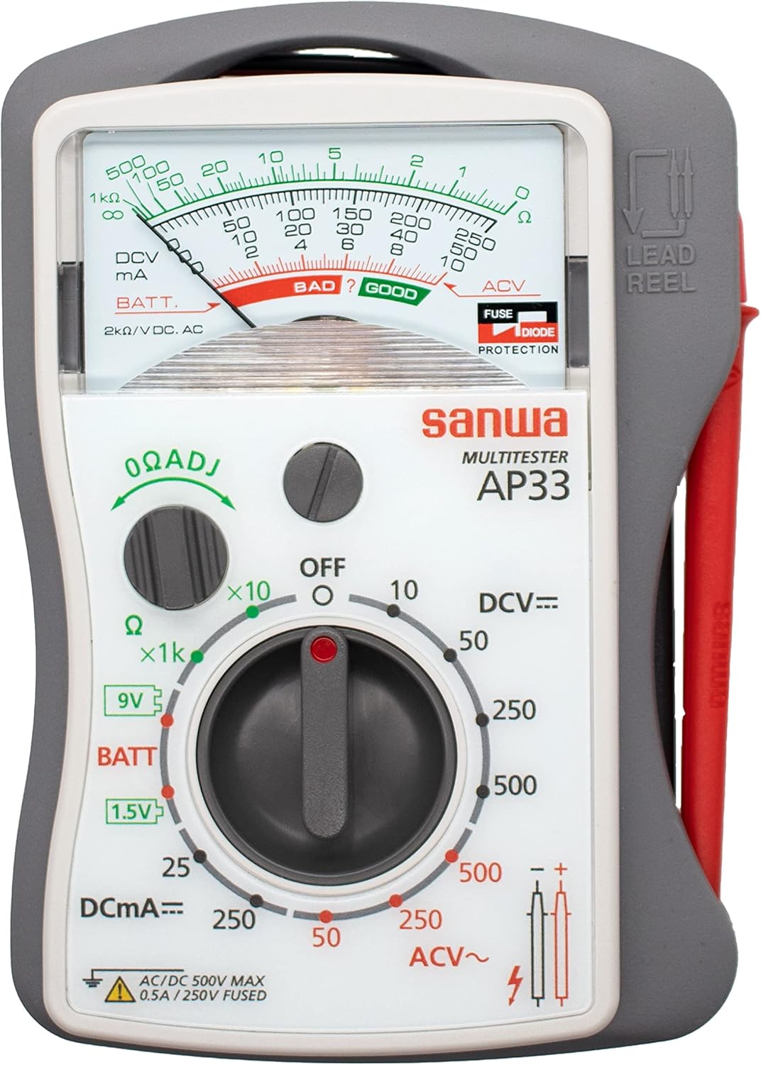
Figure 3.1: Front view of the Sanwa AP-33 Analog Multimeter, showing the dial, scale, and lead reel.

Figure 3.2: Labeled diagram of the Sanwa AP-33 components.
3.1. Component Identification
- Scale Plate: Displays measurement readings.
- Pointer: Indicates the measured value on the scale.
- Meter Zero Adjuster: Used to set the pointer to zero when no input is applied.
- 0Ω Adjuster: Used to zero the resistance reading before measurement.
- Dial Switch: Selects the measurement function (DCV, ACV, DCmA, Ω, BATT) and range.
- Test Leads (Red & Black): Used to connect the multimeter to the circuit under test. Lead length is approximately 600mm.
- Test Probes: Tips of the test leads. Rod length is 80mm.
- Pin Cap: Protects the test pin.
- Lead Holder (Manual Winding Type): Integrated into the main unit for convenient storage of test leads.
4. Setup
4.1. Battery Installation
The Sanwa AP-33 requires one AAA (R03) 1.5V battery. The battery is typically included and pre-installed. If replacement is needed:
- Ensure the multimeter is OFF and test leads are disconnected.
- Locate the battery compartment cover on the back of the unit.
- Open the cover and insert the AAA battery, observing correct polarity (+/-).
- Close the battery compartment cover securely.
4.2. Test Lead Connection and Storage
The test leads are permanently attached to the main unit and can be wound around the integrated lead holder for storage. The pin tip metal part length can be adjusted by attaching or detaching the cylindrical cap.

Figure 4.1: Sanwa AP-33 with test leads extended for use.
5. Operating Instructions
Before any measurement, ensure the meter's pointer is at zero. Use the Meter Zero Adjuster if necessary. For resistance measurements, short the test leads and use the 0Ω Adjuster to set the pointer to zero on the resistance scale.

Figure 5.1: Close-up view of the analog scale for reading measurements.
5.1. Measuring DC Voltage (DCV)
- Set the dial switch to the desired DCV range (10V, 50V, 250V, or 500V). Choose a range higher than the expected voltage.
- Connect the red test lead to the positive (+) side of the circuit and the black test lead to the negative (-) side.
- Read the voltage value on the appropriate DCV scale.
5.2. Measuring AC Voltage (ACV)
- Set the dial switch to the desired ACV range (50V, 250V, or 500V). Choose a range higher than the expected voltage.
- Connect the test leads across the AC voltage source. Polarity does not matter for AC voltage.
- Read the voltage value on the appropriate ACV scale.
5.3. Measuring DC Current (DCmA)
WARNING: Never connect the multimeter in parallel with a voltage source when measuring current. This can blow the fuse or damage the meter.
- Set the dial switch to the desired DCmA range (25mA or 250mA).
- Open the circuit where current is to be measured.
- Connect the multimeter in series with the circuit, ensuring the red lead is towards the higher potential and the black lead towards the lower potential.
- Read the current value on the appropriate DCmA scale.
5.4. Measuring Resistance (Ω)
- Set the dial switch to the desired Ω range (x10 or x1k).
- Before measuring, short the test leads together and use the 0Ω Adjuster to set the pointer to zero on the resistance scale.
- Connect the test leads across the component whose resistance is to be measured. Ensure the component is de-energized.
- Read the resistance value on the Ω scale and multiply by the range factor (x10 or x1k).
5.5. Battery Check (BATT)
- Set the dial switch to the BATT position (1.5V or 9V).
- Connect the red test lead to the positive (+) terminal of the battery and the black test lead to the negative (-) terminal.
- Read the battery condition on the 'BAD ? GOOD' scale.
6. Maintenance
6.1. Cleaning
Wipe the meter with a dry, soft cloth. Do not use abrasives or solvents.
6.2. Battery Replacement
Refer to Section 4.1 for battery replacement instructions. Always replace with a fresh AAA (R03) 1.5V battery.
6.3. Fuse Replacement
The multimeter contains a built-in fuse (0.5A 250V, φ5×20mm, breaking capacity 35A) for current protection. If the current measurement function fails, the fuse may need replacement. Fuse replacement should only be performed by qualified personnel.
6.4. Storage
When not in use for extended periods, remove the battery to prevent leakage. Store the multimeter in a cool, dry place, away from direct sunlight and extreme temperatures.
7. Troubleshooting
- No reading / Meter not turning on: Check battery installation and ensure the battery is not depleted. Replace if necessary.
- Incorrect reading: Ensure the correct function and range are selected. Verify test lead connections. Perform zero adjustment for resistance.
- Current measurement not working: Check the internal fuse. If blown, replace with a fuse of the same rating.
- Pointer not at zero: Use the Meter Zero Adjuster (for voltage/current) or 0Ω Adjuster (for resistance) to calibrate.
8. Specifications

Figure 8.1: Detailed technical specifications table for the Sanwa AP-33.
| Measurement Item | Measurement Range | Tolerance | Remarks |
|---|---|---|---|
| DC Voltage (DCV) | 10V, 50V, 250V, 500V | Within ±5% of full scale | 2kΩ/V |
| AC Voltage (ACV) | 50V, 250V, 500V | Within ±5% of full scale | 2kΩ/V |
| DC Current (DCmA) | 25mA, 250mA | Within ±5% of full scale | |
| Resistance (Ω) | 10k (×10), 1MΩ (×1k) | Within ±3% of scale length | |
| Battery Check | 1.5V (RL=14Ω), 9V (RL=420Ω) | Approximate value |
8.1. General Specifications
- Meter Type: Moving coil pivot type
- AC Rectification Method: Half-wave rectification
- Guaranteed Accuracy Temp/Humidity: 23±2℃, 70%RH or less (non-condensing)
- Operating Temp/Humidity: 5~40℃, 80%RH or less (non-condensing)
- Storage Temp/Humidity: -10~50℃, 70%RH or less (non-condensing)
- Power Supply: AAA (R03) 1.5V x 1 (included)
- Built-in Fuse: 0.5A 250V, φ5×20mm, Breaking capacity 35A
- Test Leads: Pin tip: φ2mm×13mm, Lead length: approx 600mm (fixed to main unit)
- Dimensions (H×W×D): 126mm × 87mm × 30mm (approx. 4.96 x 3.43 x 1.18 inches)
- Mass: Approx. 185g (approx. 6.5 ounces) (main unit)
- Accessories: Test leads (fixed), Battery, Instruction manual
- Safety Standard: IEC 61010-1
8.2. Additional Features
- Palm-sized, fits in workwear chest pockets.
- Test leads can be wound and stored in the main unit.
- Pin tip metal part length can be adjusted by attaching/detaching cylindrical cap.
9. Warranty and Support
For warranty information and technical support, please refer to the documentation provided with your purchase or contact your local Sanwa distributor. Keep your purchase receipt as proof of purchase.


