1. Introduction
This manual provides comprehensive instructions for the installation, operation, and maintenance of the Allied Telesis AT-MC102XL-90 Fast Ethernet Media Converter. This device is designed to extend the reach of your UTP (Unshielded Twisted Pair) network by converting 100Base-TX signals to 100Base-FX (SC) fiber optic signals, allowing for network connections over longer distances up to 1.2 miles.
2. Product Overview
The AT-MC102XL-90 is a compact and reliable media converter that facilitates seamless integration between copper-based Fast Ethernet networks and fiber optic networks. It supports a data transfer rate of 100 Mbps.

Figure 1: Front view of the Allied Telesis AT-MC102XL-90 Media Converter, showing the 100Base-FX SC ports, 100Base-TX RJ-45 port, LED indicators (FDX, LINK, PWR, ACT, M/L ON), and switches (LINK TST, A/N ON/OFF).
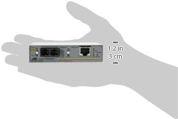
Figure 2: The Allied Telesis AT-MC102XL-90 Media Converter shown in a hand, illustrating its compact size and dimensions (approximately 1.2 inches / 3 cm in height).
2.1 Key Components and Indicators
- 100Base-FX Ports (SC): Two SC fiber optic connectors for fiber cable connection.
- 100Base-TX Port (RJ-45): Standard RJ-45 connector for UTP Ethernet cable connection.
- PWR LED: Indicates power status.
- LINK LED (TX/FX): Indicates a valid link on the respective copper (TX) or fiber (FX) port.
- ACT LED (TX/FX): Indicates activity (data transmission/reception) on the respective copper (TX) or fiber (FX) port.
- FDX LED: Indicates Full-Duplex operation.
- M/L ON Switch: MissingLink feature enable/disable switch.
- A/N ON/OFF Switch: Auto-Negotiation feature enable/disable switch.
- LINK TST Button: Link Test button for diagnostic purposes.
3. Setup and Installation
- Power Connection: Connect the provided power adapter to the media converter and then to a power outlet. The PWR LED should illuminate.
- UTP Cable Connection: Connect a standard Fast Ethernet (100Base-TX) UTP cable from your network device (e.g., switch, router) to the RJ-45 port on the media converter. Ensure the LINK LED for the TX port illuminates.
- Fiber Optic Cable Connection: Connect a 100Base-FX SC fiber optic cable to the SC ports on the media converter. Ensure the LINK LED for the FX port illuminates. Observe proper fiber polarity (TX to RX, RX to TX).
- Auto-Negotiation Setting: The A/N ON/OFF switch controls the Auto-Negotiation feature.
- ON: The converter will attempt to auto-negotiate speed and duplex settings with the connected device. This is the recommended setting for most installations.
- OFF: The converter will operate at a fixed speed and duplex. Ensure the connected device is also configured for fixed settings to avoid communication issues.
Important: Always ensure all cables are securely connected before powering on the device. Incorrect cable connections or settings can prevent proper network operation.
4. Operating Instructions
4.1 LED Indicators
- PWR (Power):
- Solid Green: Device is powered on.
- Off: Device is not receiving power.
- LINK (TX/FX):
- Solid Green: A valid network link is established on the respective port.
- Off: No link detected. Check cable connections and connected device status.
- ACT (TX/FX):
- Flashing Green: Data is being transmitted or received on the respective port.
- Off: No network activity.
- FDX (Full-Duplex):
- Solid Green: The port is operating in Full-Duplex mode.
- Off: The port is operating in Half-Duplex mode.
4.2 M/L ON (MissingLink) Switch
The MissingLink feature allows the media converter to monitor the link status of both the copper and fiber connections. If one link fails, the converter can automatically disable the other link, preventing data from being sent over a broken path and allowing upstream devices to detect the link failure.
- ON: MissingLink feature is enabled.
- OFF: MissingLink feature is disabled.
4.3 LINK TST (Link Test) Button
Pressing the LINK TST button can help diagnose connectivity issues by initiating a link test. Refer to the device's advanced documentation for specific diagnostic procedures related to this feature.
5. Maintenance
- Cleaning: Keep the device clean and free from dust. Use a soft, dry cloth for cleaning. Do not use liquid cleaners.
- Environment: Ensure the converter is operated within its specified environmental conditions (temperature, humidity) to prevent damage and ensure optimal performance. Avoid placing it in direct sunlight or near heat sources.
- Cable Management: Ensure all cables are properly routed and secured to prevent accidental disconnections or damage.
6. Troubleshooting
- No Power (PWR LED Off):
- Check if the power adapter is securely connected to the converter and the power outlet.
- Verify the power outlet is functional.
- No Link (LINK LED Off):
- Ensure the Ethernet (RJ-45) and fiber (SC) cables are correctly and securely connected.
- Verify the connected network devices (switch, router, fiber equipment) are powered on and functioning correctly.
- Check the A/N ON/OFF switch setting. If set to OFF, ensure both devices are configured for the same fixed speed and duplex.
- For fiber connections, ensure correct fiber polarity (TX to RX, RX to TX).
- Inspect cables for damage.
- No Activity (ACT LED Off when data is expected):
- Confirm that data is actively being transmitted through the network.
- Check the link status (LINK LED). If no link, resolve link issues first.
- Verify network device configurations.
- Network Performance Issues:
- Ensure the FDX LED is on if full-duplex operation is desired and supported by both connected devices. Mismatched duplex settings can cause performance degradation.
- Check for excessive cable lengths or poor quality cables.
7. Specifications
| Feature | Description |
|---|---|
| Model Number | AT-MC102XL-90 |
| Product Type | Fast Ethernet Media Converter |
| Brand | Allied Telesis |
| Data Transfer Rate | 100 Mbps |
| Connectivity Technology | Wired |
| Interfaces | 1 x 100Base-TX (RJ-45), 1 x 100Base-FX (SC) |
| Max Transfer Distance | Up to 1.2 miles (fiber) |
| Product Dimensions | 3.74 x 4.13 x 0.98 inches (9.5 x 10.5 x 2.5 cm) |
| Item Weight | 10.4 ounces (295 grams) |
| Manufacturer | Allied Telesyn International |
| Country of Origin | Singapore |
8. Warranty and Support
The Allied Telesis AT-MC102XL-90 Media Converter comes with a Limited Lifetime Warranty. For detailed warranty terms and conditions, please refer to the official Allied Telesis website or contact their customer support.
For technical support, troubleshooting assistance, or further inquiries, please contact Allied Telesis customer service through their official channels. Ensure you have your product model number (AT-MC102XL-90) available when seeking support.


