1. Introduction
The Design Engineering CryO2 3" O.D. Cryogenic Air Intake is designed to enhance engine performance by cooling the intake air charge. This system utilizes a patented cryogenic chamber within an aerodynamically designed bulb, which is integrated into a 4-inch segment of air tube. As air flows over the bulb, heat is removed, resulting in a colder, denser air charge for improved combustion efficiency. This product is suitable for turbocharged, supercharged, and normally aspirated applications.
2. Safety Information
Please read and understand all safety warnings and instructions before installing or operating this product. Failure to do so may result in property damage, personal injury, or death.
- Always wear appropriate personal protective equipment (PPE), including safety glasses and gloves, during installation.
- Ensure the vehicle's engine is off and cool before beginning installation.
- Handle cryogenic components with care. Avoid direct skin contact with extremely cold surfaces to prevent frostbite.
- Ensure all connections are secure and leak-free to prevent accidental release of cryogenic agents.
- Do not modify the product in any way. Use only genuine Design Engineering replacement parts.
- Keep out of reach of children.
3. Package Contents
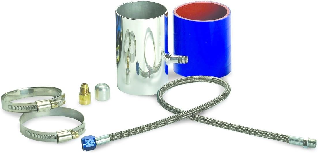
Verify that all components listed below are present in your package:
- CryO2 Air Intake Unit (aerodynamically designed bulb with cryogenic chamber in a 4" air tube segment)
- Silicone Connection Sleeve
- Hose Clamps (2)
- Connection/Vent Hose
- Fittings (if applicable, for connection to cryogenic source)
4. Setup and Installation
Follow these steps for proper installation of the CryO2 Air Intake system:
- Preparation: Ensure the vehicle's engine is completely cool. Disconnect the negative terminal of the battery. Identify a suitable location in your vehicle's air intake system where the 4-inch segment of the CryO2 Air Intake can be integrated. This typically involves cutting an existing section of the intake tube.
- Cutting the Intake Tube: Carefully measure and mark the section of your vehicle's existing air intake tube where the CryO2 unit will be installed. Cut the tube cleanly and precisely to accommodate the 4-inch length of the CryO2 unit. Ensure there are no burrs or sharp edges.
- Installing the CryO2 Unit: Slide one hose clamp onto each end of the silicone connection sleeve. Place the silicone sleeve onto one end of the cut air intake tube. Insert the CryO2 Air Intake unit into the silicone sleeve, ensuring a snug fit. Then, connect the other end of the silicone sleeve to the remaining section of the vehicle's air intake tube.
- Securing Connections: Position the hose clamps over the silicone sleeve and the air intake tubes/CryO2 unit. Tighten the hose clamps securely using an appropriate tool, ensuring a tight, leak-free seal. Do not overtighten.
- Connecting the Cryogenic Source: Attach the provided connection/vent hose to the fitting on the CryO2 Air Intake unit. Route the hose to your cryogenic source (e.g., a CO2 bottle, sold separately) following the instructions provided with your cryogenic system. Ensure all fittings are tightened to prevent leaks.
- Final Checks: Double-check all connections for security and proper fitment. Ensure no hoses are kinked or pinched. Reconnect the negative terminal of the battery.
5. Operating Instructions
The CryO2 Air Intake system operates by cooling the incoming air charge. Its function is dependent on the activation of your connected cryogenic system (e.g., CO2 injection). Refer to the operating instructions of your specific cryogenic system for details on activation and usage.
- Ensure your cryogenic source is adequately filled and properly connected.
- Activate the cryogenic system according to its manufacturer's instructions. The CryO2 Air Intake unit will then begin to cool the air passing through it.
- Monitor your vehicle's performance and intake air temperatures (if equipped with a sensor) to observe the effects of the system.
6. Maintenance
The CryO2 Air Intake unit requires minimal maintenance. Regular inspection is recommended to ensure optimal performance and safety.
- Periodic Inspection: Regularly inspect all hose connections and clamps for tightness and signs of wear or damage.
- Cleaning: If the exterior of the unit becomes dirty, wipe it with a soft, damp cloth. Do not use abrasive cleaners or solvents.
- Cryogenic Source: Ensure your cryogenic supply (e.g., CO2 bottle) is refilled or replaced as needed, following the supplier's guidelines.
7. Troubleshooting
If you encounter issues with your CryO2 Air Intake system, consider the following common problems and solutions:
| Problem | Possible Cause | Solution |
|---|---|---|
| No noticeable temperature drop. | Cryogenic source empty or not activated. Leaks in the cryogenic supply line. | Check cryogenic bottle level and ensure system is activated. Inspect all fittings and hoses for leaks and tighten as necessary. |
| Air intake unit feels warm. | Cryogenic flow insufficient or absent. | Verify cryogenic system operation and supply. |
| Loose connections. | Hose clamps or fittings not tightened sufficiently. | Inspect and tighten all hose clamps and fittings. |
If problems persist, contact Design Engineering customer support.
8. Specifications
- Model Number: 080110 (also referred to as 80110)
- Outer Diameter (O.D.): 3 inches
- Product Dimensions: Approximately 22.86 x 15.24 x 13.97 cm (9 x 6 x 5.5 inches)
- Item Weight: Approximately 580 g (1.28 lbs)
- Material: Aerodynamically designed bulb with cryogenic chamber, silicone connection sleeve.
- Application: Turbocharged, supercharged, and normally aspirated engines.
- Temperature Reduction: Up to 50°F (typical, based on testing)
9. Warranty and Support
Design Engineering products are manufactured to high standards. For specific warranty information, please refer to the warranty card included with your product or visit the official Design Engineering website. Keep your proof of purchase for warranty claims.
For technical support, installation assistance, or to inquire about replacement parts, please contact Design Engineering customer service:
- Website: www.designengineering.com
- Phone: Refer to the website for regional contact numbers.
- Address: Design Engineering, Inc., AVON LAKE, OH, 44012 US


