1. Introduction
This manual provides detailed instructions for the installation and proper use of the Pyle PLAM40 Car Stereo Wiring Kit. This kit is designed to facilitate the connection of car audio amplifiers and subwoofer speakers within a vehicle's electrical system. Please read this manual thoroughly before beginning installation to ensure safe and correct setup.
2. Safety Information
WARNING:
- Always disconnect the vehicle's negative battery terminal before beginning any electrical installation.
- Ensure all wiring connections are secure and properly insulated to prevent short circuits.
- Route cables away from moving parts, sharp edges, and heat sources.
- Use appropriate personal protective equipment, such as safety glasses and gloves.
- Consult a professional if you are unsure about any part of the installation process.
- This product contains chemicals known to the State of California to cause cancer and birth defects or other reproductive harm.
3. Package Contents
The Pyle PLAM40 Car Stereo Wiring Kit includes the following components:

Image Description: This image displays the complete Pyle PLAM40 Car Stereo Wiring Kit, including the retail box and all individual components laid out. Key items visible are various lengths of red, black, and blue wires, RCA cables, an AGU fuse holder, a 60A gold-plated fuse, ring and spade terminals, butt connectors, cable ties, and a black grommet.
- 20 ft. 4 Gauge Red Power Wire
- 4 ft. 4 Gauge Black Ground Wire
- 20 ft. 16 Gauge Blue Remote Turn-On Wire
- 20 ft. 12 Gauge Stereo Speaker Wire
- 20 ft. Stereo RCA Audio Cable (Male to Male)
- 6 ft. Black Split Loom Cable Conduit
- AGU Type 60A Gold Plated Fuse
- In-Line Water Resistant Fuse Holder
- 2 Ring Terminals: 4 Gauge
- 2 Spade Terminals: 4 Gauge
- 5 Spade Terminals: 16-18 Gauge
- 3 Butt Connectors
- 20 Cable Ties
- 1 Black Grommet

Image Description: This image shows a close-up of the main cables provided in the kit, including the red power wire, black ground wire, blue remote turn-on wire, stereo speaker wire, and RCA audio cables, all coiled neatly.
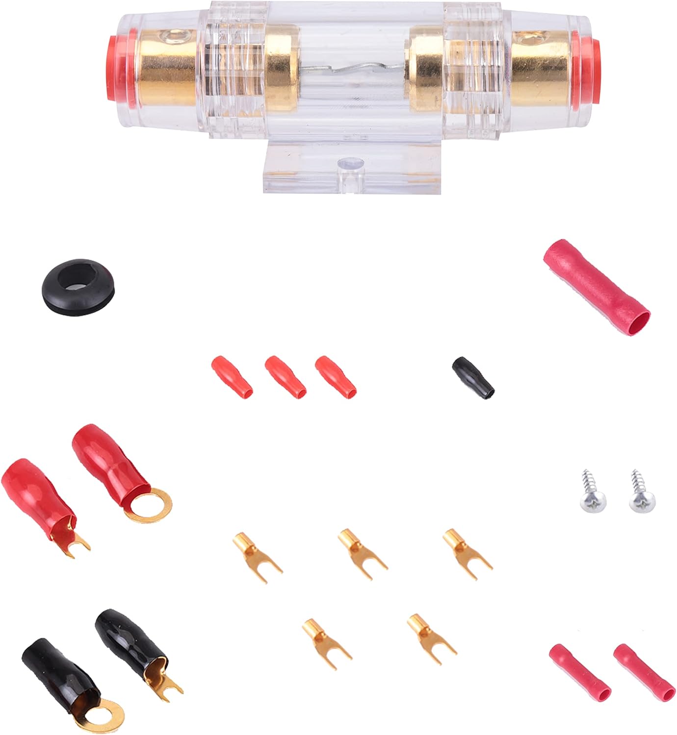
Image Description: This image details the smaller components of the kit, such as the AGU fuse holder, various ring and spade terminals, butt connectors, cable ties, and the black grommet, laid out for clear identification.
4. Setup and Installation
This section outlines the general steps for installing your car audio amplifier and subwoofer using the Pyle PLAM40 wiring kit. Specific vehicle configurations may vary.
4.1. Planning the Installation
- Determine the mounting location for your amplifier, ensuring adequate ventilation and protection from moisture.
- Plan the routing of all cables to minimize interference and ensure safety. Avoid sharp bends and areas prone to pinching.
4.2. Power Wire Installation
- Disconnect Battery: Disconnect the negative (-) terminal of your vehicle's battery.
- Route Power Wire: Route the 20 ft. 4 Gauge Red Power Wire from the battery location through the firewall into the vehicle's interior to the amplifier mounting location. Use the black grommet where the wire passes through the firewall to protect it from abrasion.
- Install Fuse Holder: Install the In-Line Water Resistant Fuse Holder within 18 inches (45 cm) of the battery's positive (+) terminal. Connect one end of the power wire to one side of the fuse holder and a short length of power wire (from the kit) to the other side.
- Connect to Battery: Attach a 4 Gauge Ring Terminal to the short length of power wire and connect it to the positive (+) terminal of the battery.
- Insert Fuse: Insert the AGU Type 60A Gold Plated Fuse into the fuse holder.

Image Description: This diagram illustrates the complete wiring setup for a car audio system. It shows the battery connected to the fuse holder, which then connects to the amplifier via the power cable. The amplifier is grounded to the chassis. RCA cables connect the receiver to the amplifier, and speaker wires connect the amplifier to the speakers and subwoofer. A remote turn-on wire connects the receiver to the amplifier.

Image Description: This image focuses on the power cable connection. It shows the red power cable connected to the car battery's positive terminal via a ring terminal, leading to the water-resistant in-line fuse holder. The fuse holder contains an AGU fuse, protecting the circuit.
4.3. Ground Wire Installation
- Route Ground Wire: Route the 4 ft. 4 Gauge Black Ground Wire from the amplifier mounting location to a clean, unpainted metal surface on the vehicle's chassis.
- Prepare Ground Point: Scrape away any paint or rust from the chosen ground point to ensure a good electrical connection.
- Connect Ground Wire: Attach a 4 Gauge Ring Terminal to the ground wire and securely fasten it to the prepared chassis ground point using a self-tapping screw or existing bolt.
4.4. Remote Turn-On Wire Installation
- Connect to Head Unit: Connect one end of the 20 ft. 16 Gauge Blue Remote Turn-On Wire to the remote output terminal of your car's head unit (stereo).
- Route to Amplifier: Route the wire to the amplifier's remote input terminal.

Image Description: This image shows the blue remote turn-on wire connected from the car stereo (head unit) to the amplifier's remote input terminal. This wire signals the amplifier to turn on when the stereo is activated.
4.5. RCA Audio Cable Installation
- Connect to Head Unit: Connect the RCA plugs of the 20 ft. Stereo RCA Audio Cable (Male to Male) to the RCA pre-out jacks on your car's head unit.
- Route to Amplifier: Route the RCA cables to the RCA input jacks on your amplifier. Try to route RCA cables on the opposite side of the vehicle from power cables to minimize noise interference.
4.6. Speaker Wire Installation
- Connect to Amplifier: Connect the 20 ft. 12 Gauge Stereo Speaker Wire to the speaker output terminals on your amplifier.
- Route to Speakers/Subwoofer: Route the speaker wires to your speakers and/or subwoofer. Ensure correct polarity (+ to + and - to -) for all connections.
- Connect to Speakers: Connect the speaker wires to the terminals on your speakers/subwoofer. Use the provided spade terminals (16-18 Gauge) for smaller speaker connections if needed.

Image Description: This image shows a close-up of speaker wires connected to a car speaker. The wires are typically connected to the positive and negative terminals of the speaker, ensuring proper audio signal transmission.
4.7. Cable Management
- Use the 6 ft. Black Split Loom Cable Conduit to protect wires in areas where they might be exposed to heat or abrasion.
- Secure all cables using the provided 20 Cable Ties to prevent them from moving or interfering with vehicle operation.
5. Operating Your Audio System
Once all connections are made and secured, reconnect the negative (-) battery terminal. Turn on your car's ignition and then the head unit. The amplifier should power on automatically via the remote turn-on wire. Adjust amplifier gain and crossover settings according to your audio preferences and speaker specifications.
6. Maintenance
- Periodically inspect all wiring connections for tightness and corrosion.
- Check the fuse in the in-line fuse holder. If the fuse blows, replace it only with an AGU type 60A fuse. Do not use a fuse with a higher amperage rating.
- Keep cables clean and free from debris.
7. Troubleshooting
| Problem | Possible Cause | Solution |
|---|---|---|
| Amplifier does not turn on. | Blown fuse in fuse holder. | Check and replace the 60A AGU fuse. |
| Amplifier does not turn on. | Loose or disconnected power/ground/remote wire. | Verify all power, ground, and remote turn-on connections are secure. |
| No sound from speakers. | Loose or incorrect RCA/speaker wire connections. | Check RCA cables from head unit to amplifier and speaker wires from amplifier to speakers for proper connection and polarity. |
| Engine noise (whining) through speakers. | Poor ground connection or RCA cables routed too close to power cables. | Ensure ground connection is clean and secure. Reroute RCA cables away from power cables if possible. |
8. Specifications
| Component | Detail |
|---|---|
| Power Wire | 20 ft., 4 Gauge, Red |
| Ground Wire | 4 ft., 4 Gauge, Black |
| Remote Turn-On Wire | 20 ft., 16 Gauge, Blue |
| Stereo Speaker Wire | 20 ft., 12 Gauge |
| RCA Audio Cable | 20 ft., Male to Male |
| Split Loom Cable Conduit | 6 ft., Black |
| Fuse Type | AGU Type, 60A, Gold Plated |
| Fuse Holder | In-Line, Water Resistant |
| Model Number | PLAM40 |
| Brand | Pyle |
| Item Weight | 1 Pounds (approx. 0.45 kg) |
| Product Dimensions | 8.9 x 8.5 x 2.3 inches (approx. 22.6 x 21.6 x 5.8 cm) |
9. Warranty and Support
The Pyle PLAM40 Car Stereo Wiring Kit comes with a ONE YEAR warranty from the date of purchase. For warranty claims or technical support, please contact Pyle customer service. You can find more information and contact details on the official Pyle website: www.pyleusa.com.
For additional resources and product information, visit the Pyle Store on Amazon: Pyle Store.


