1. Product Overview
The Holley Model 2300 500 CFM 2-Barrel Manual Choke Carburetor, model 0-4412S, is engineered as a direct replacement for 2-barrel street applications and is also approved for certain oval track racing sanctioning bodies. This carburetor is designed to provide reliable performance, whether replacing an existing unit or enhancing a vehicle's fuel system for competitive use.

Figure 1.1: Front view of the Holley Model 2300 Carburetor. This image displays the overall design and shiny finish of the carburetor, highlighting its primary components.
2. Key Features
- Model 2300 with Center Hung Float: Ensures consistent fuel level control under various driving conditions.
- Manual Choke: Provides precise control over engine warm-up, allowing for easier cold starts and improved drivability.
- Ford A/T Kickdown: Designed for compatibility with Ford automatic transmissions, ensuring proper downshifting.
- Power Valve Blow-Out Protection: Enhances durability and reliability by preventing damage to the power valve during backfires.
- 50cc Accelerator Pump: Delivers a strong, immediate fuel shot for improved throttle response.
- Universal Calibration: Offers broad compatibility with various engine setups.
- 100% Wet-Flow Tested and Calibrated: Each unit is tested to ensure optimal performance right out of the box.
- Shiny Finish: Provides a durable and aesthetically pleasing appearance.

Figure 2.1: Side view of the carburetor highlighting the manual choke mechanism and accelerator pump. This image provides a closer look at the external components responsible for fuel delivery and engine control.
3. Installation Guide
Proper installation is crucial for the optimal performance of your Holley carburetor. It is recommended that installation be performed by a qualified automotive technician. Always ensure the engine is cool and the battery is disconnected before beginning any work.
3.1 Pre-Installation Checks
- Verify the carburetor's compatibility with your vehicle's engine and intake manifold.
- Inspect the intake manifold for flatness and cleanliness.
- Ensure all necessary gaskets, studs, and linkage components are available.
3.2 Mounting the Carburetor
- Remove the old carburetor and clean the mounting surface thoroughly.
- Place the new carburetor gasket onto the intake manifold studs.
- Carefully lower the Holley 0-4412S carburetor onto the studs, ensuring it seats properly on the gasket.
- Install the retaining nuts and tighten them evenly in a crisscross pattern to the manufacturer's specified torque.
3.3 Linkage and Fuel Line Connection
- Connect the throttle linkage and ensure smooth, unrestricted movement from idle to wide-open throttle.
- Attach the fuel line to the single feed fuel inlet, ensuring a secure, leak-free connection.
- Connect the manual choke cable and adjust for proper operation.
- If applicable, connect the Ford A/T kickdown linkage.

Figure 3.1: Diagram illustrating the mounting pattern and dimensions for the 2-barrel carburetor. This is essential for verifying fitment with your intake manifold.

Figure 3.2: Side view of the carburetor, detailing the throttle linkage and manual choke connection points. Proper connection of these linkages is vital for vehicle operation.
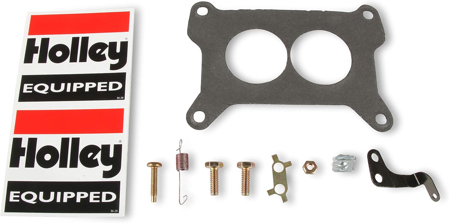
Figure 3.3: Included components and hardware, such as gaskets and small parts, necessary for installation.
4. Operation and Initial Adjustment
After installation, initial adjustments are necessary to ensure proper engine operation. The Holley 0-4412S is wet-flow tested and calibrated from the factory, minimizing the need for extensive tuning.
4.1 Starting the Engine
- With the manual choke engaged (closed), crank the engine.
- Once the engine starts, gradually open the choke as the engine warms up.
- Allow the engine to reach operating temperature before making final adjustments.
4.2 Idle Speed Adjustment
Locate the idle speed screw on the carburetor. With the engine at operating temperature, turn the screw clockwise to increase idle speed or counter-clockwise to decrease it, aiming for the manufacturer's recommended RPM for your vehicle.
4.3 Idle Mixture Adjustment
The idle mixture screws control the air/fuel ratio at idle. Turn them in (clockwise) until the engine begins to stumble, then back them out (counter-clockwise) until the engine runs smoothly. Repeat for both screws, ensuring they are adjusted equally. This adjustment affects only the idle circuit and not the main fuel curve.
5. Maintenance
Regular maintenance ensures the longevity and optimal performance of your Holley carburetor.
- Fuel Filter Replacement: Periodically replace the inline fuel filter to prevent contaminants from reaching the carburetor.
- Air Filter Inspection: Ensure the air filter is clean and free of obstructions. A dirty air filter can affect carburetor performance.
- Linkage Lubrication: Lubricate all moving linkage points with a suitable lubricant to ensure smooth operation and prevent wear.
- Visual Inspection: Regularly inspect the carburetor for any signs of fuel leaks, loose connections, or damaged components.
- Cleaning: Use a carburetor cleaner to remove any varnish or carbon deposits that may accumulate over time. Always follow the cleaner manufacturer's instructions.
6. Troubleshooting
This section addresses common issues you might encounter with your carburetor.
| Symptom | Possible Cause | Solution |
|---|---|---|
| Engine runs rough at idle / Stalls | Incorrect idle mixture setting, vacuum leak, dirty idle circuit. | Adjust idle mixture screws. Check for vacuum leaks. Clean idle passages. |
| Engine runs too rich (black smoke, strong fuel smell) | Float level too high, stuck power valve, incorrect jetting. | Check and adjust float level. Inspect power valve. Consider smaller main jets if persistent. |
| Engine runs too lean (hesitation, backfiring) | Float level too low, clogged fuel filter, vacuum leak, incorrect jetting. | Check and adjust float level. Replace fuel filter. Check for vacuum leaks. Consider larger main jets. |
| Hard starting (cold) | Improper choke adjustment, weak accelerator pump shot. | Adjust manual choke cable. Verify accelerator pump operation. |
7. Technical Specifications
| Specification | Detail |
|---|---|
| Brand | Holley |
| Model Name | Holley HOL 0-4412S 0-4412S Model 2300 500 CFM 2-Barrel Manual Choke New Carburetor |
| OEM Part Number | 0-4412S |
| Fuel Type | Gasoline |
| Exterior Finish | Machined |
| Item Weight | 5.4 Pounds (2.45 kg) |
| Item Package Dimensions | 12.4 x 11.15 x 7.75 inches (31.5 x 28.3 x 19.7 cm) |
| Automotive Fit Type | Vehicle Specific Fit |
| UPC | 090127425718 |

Figure 7.1: Top view of the carburetor, illustrating the two barrels and internal components. This view is useful for understanding air and fuel flow paths.

Figure 7.2: Bottom view of the carburetor, displaying the mounting surface and bolt holes. This perspective is critical for proper gasket alignment and installation.
8. Warranty Information
This Holley carburetor comes with a limited warranty. For specific details regarding coverage, duration, and claims procedures, please refer to the warranty documentation included with your purchase or contact Holley customer support directly. Keep your proof of purchase for warranty claims.
9. Safety Information
CALIFORNIA WARNING: Cancer and Reproductive Harm - www.P65Warnings.ca.gov
Always wear appropriate personal protective equipment (PPE) such as safety glasses and gloves when handling or installing automotive components. Ensure adequate ventilation when working with fuel and carburetor cleaners. Keep all flammable materials away from open flames or ignition sources. Dispose of all fluids and waste materials according to local environmental regulations.


