Introduction
This manual provides essential information for the proper installation, operation, and maintenance of your VDO 340 001 Speedometer/Tachometer Generator Sender. This device is designed to generate electrical pulses corresponding to rotational speed, which are then interpreted by compatible speedometer or tachometer gauges.
Please read these instructions thoroughly before installation and keep this manual for future reference.
Product Overview
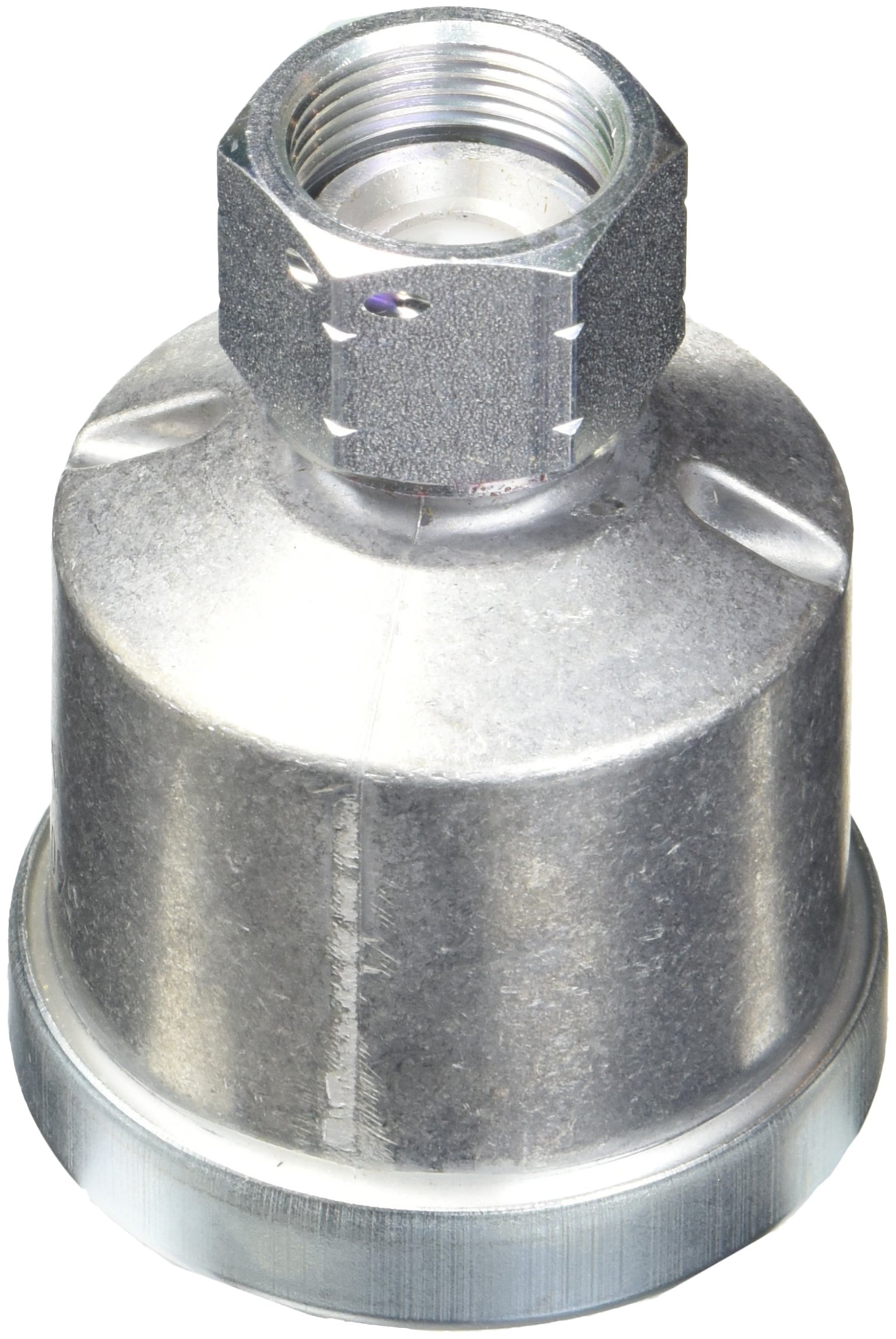
Figure 1: VDO 340 001 Speedometer/Tachometer Generator Sender. This image shows the sender unit with its threaded body and electrical connector.
The VDO 340 001 is a pulse generator sender unit. It features a 7/8-18 thread for secure mounting and is designed to operate with a 12-volt electrical system. Its primary function is to convert mechanical rotation into an electrical signal for accurate speed or RPM measurement.
Setup and Installation
Proper installation is crucial for the accurate and reliable operation of the VDO 340 001 sender. Consult your vehicle or equipment service manual for specific mounting locations and wiring diagrams.
Tools and Materials Required:
- Wrench (appropriate size for 7/8-18 thread)
- Wire strippers/crimpers
- Electrical connectors (as needed)
- Multimeter (for testing connections)
- Thread sealant (optional, for watertight seal)
Installation Steps:
- Identify Mounting Location: Locate the designated mounting point for the speedometer/tachometer sender on your transmission, engine, or other rotating component. Ensure the area is clean and free of debris.
- Thread Engagement: Carefully thread the VDO 340 001 sender into the mounting hole. Ensure it engages smoothly without cross-threading.
- Tighten Securely: Using an appropriate wrench, tighten the sender firmly. Do not overtighten, as this can damage the sender or the mounting point. If using thread sealant, apply it according to the sealant manufacturer's instructions.
- Electrical Connection:
- Connect the sender's output wire to the signal input of your compatible speedometer or tachometer.
- Connect the sender's ground wire to a reliable chassis ground.
- Ensure all electrical connections are secure and properly insulated to prevent short circuits and corrosion.
- Power Supply: Verify that the connected gauge receives a stable 12-volt power supply. The sender itself is typically passive, generating a signal based on rotation, but the gauge requires power.
- Test Functionality: After installation, perform a functional test to ensure the sender is providing an accurate signal to the gauge.
Caution: Incorrect wiring can damage the sender, the gauge, or other electrical components. If you are unsure about any step, consult a qualified automotive technician.
Operating Instructions
The VDO 340 001 Speedometer/Tachometer Generator Sender operates automatically once installed and connected to a compatible gauge. It does not require manual user interaction for its primary function.
- As the connected mechanical component rotates, the sender generates electrical pulses.
- These pulses are transmitted to the speedometer or tachometer gauge.
- The gauge interprets the frequency of these pulses to display speed or RPM.
Ensure that the gauge is properly calibrated according to its own instruction manual to match the pulse output of the VDO 340 001 sender for accurate readings.
Maintenance
The VDO 340 001 sender is designed for durability and typically requires minimal maintenance. Regular inspection can help ensure its longevity and reliable performance.
- Visual Inspection: Periodically check the sender unit for any signs of physical damage, corrosion, or loose connections.
- Wiring Integrity: Ensure that all wiring connected to the sender is intact, free from fraying, and securely attached.
- Cleanliness: Keep the area around the sender free from excessive dirt, grease, or debris that could interfere with its operation or cause premature wear.
No internal user-serviceable parts are present. Do not attempt to disassemble the sender unit.
Troubleshooting
If you experience issues with your speedometer or tachometer readings, consider the following troubleshooting steps related to the sender unit:
Common Issues and Solutions:
- No Reading on Gauge:
- Check all electrical connections to the sender and the gauge for looseness or corrosion.
- Verify that the gauge is receiving proper power and ground.
- Inspect the sender's wiring for breaks or short circuits.
- Ensure the sender is securely mounted and engaging with the rotating component.
- Erratic or Inaccurate Reading:
- Check for intermittent electrical connections or damaged wiring.
- Ensure the sender is not loose in its mounting, which could cause inconsistent signal generation.
- Verify the gauge's calibration settings.
- Inspect the sender for physical damage or obstruction that might affect its pulse generation.
If troubleshooting steps do not resolve the issue, the sender unit may be faulty and require replacement, or the issue may lie with the connected gauge or vehicle wiring system. Consult a qualified technician for further diagnosis.
Specifications
The following are the technical specifications for the VDO 340 001 Speedometer/Tachometer Generator Sender:
| Feature | Specification |
|---|---|
| Manufacturer | VDO |
| Brand | VDO |
| Model Number | 340 001 |
| OEM Part Number | 340-001 |
| Thread Size | 7/8-18 |
| Operating Voltage | 12 Volts (for connected gauge) |
| Item Weight | 12 ounces (approx. 0.34 kg) |
| Product Dimensions | 4 x 3 x 3 inches (approx. 10.16 x 7.62 x 7.62 cm) |
| Country of Origin | Made in Germany |
Warranty and Support
For information regarding warranty coverage, technical support, or replacement parts for your VDO 340 001 Speedometer/Tachometer Generator Sender, please contact VDO customer service directly or refer to the official VDO website.
Keep your purchase receipt as proof of purchase for any warranty claims.


