ALSF High-Intensity Approach Lighting System

Product Information
The product is an Approach Lighting System (ALSF) with Elevated Sequenced Flashers. It is designed according to ALSF-1, ALSF-2, ALSF-2/SSALR FAA-E-2628, FAA-E-2325 (Sequenced Flashing Components), and Annex 14 para. 5.3.4.7, 5.3.4.15, 5.3.4.16, 5.3.4.30, and 5.3.4.31 standards. It is used at airports and military air bases to provide landing approach guidance, including runway alignment, height perception, horizontal reference, and roll guidance.
Operating Conditions
- Temperature: [Temperature range]
- Humidity: [Humidity range]
- Altitude: [Altitude range]
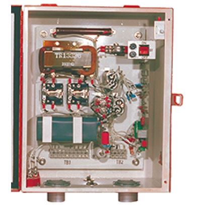
Master Control Cabinet
The Master Control Cabinet controls the flashers of the ALSF system. It can accommodate a maximum of 8, 15, or 21 flashers depending on the configuration selected. The cabinet can be ordered with or without monitoring and is available in standard or stainless steel enclosure types.
Packaging Information
| Voltage | Dimensions | Gross Weight |
|---|---|---|
| 120/240 VAC (standard) | 37.25 x 30 x 11.38 in (94.6 x 76.2 x 28.9 cm) |
137 lb (62 kg) |
| 480 VAC | 48 x 36 x 16.38 in (125.1 x 91.4 x 41.6 cm) |
279 lb (126.6 kg) |
Master Control Cabinet Equipment Data
The Master Control Cabinet requires an input voltage of 120/240 VAC (+10%), 60 Hz, three-wire, single-phase (neutral center-tapped). Optional input of 480 VAC (+10%), 60 Hz, two-wire, single-phase is available. It operates in manual (local) control and remote control modes and is enclosed in a NEMA 4 outdoor and ventilated enclosure for protection against condensation. It features maintenance features to adjust the brightness level of the system and has lightning protection on all input and output electrical connections.
Individual Control Cabinet (ICC)
Each flasher unit is controlled by an individual control cabinet (ICC) that contains triggering circuits, terminal blocks, and lightning arrestors. The ICC includes a safety interlock switch to discharge the high-voltage circuitry when the cabinet door is opened. The ICC can be ordered as an elevated flasher, elevated flasher panel only, or elevated flasher in stainless steel.
Junction Box
Junction boxes are used to distribute power and control signals to the ICCs. Each sequenced flasher in the system requires a junction box. The junction box has terminal strips to accommodate incoming and outgoing power, a control circuit, and a monitoring wire for the flasher unit.
Product Usage Instructions
To use the ALSF system with Elevated Sequenced Flashers, follow these steps:
- Ensure that the operating conditions, including temperature, humidity, and altitude, are within the specified range for the system.
- Install the Master Control Cabinet in a suitable location, considering the voltage requirements and enclosure type.
- Connect the necessary power supply to the Master Control Cabinet, either 120/240 VAC or 480 VAC.
- If monitoring is desired, select the option with monitoring when ordering the Master Control Cabinet.
- Install the Individual Control Cabinets (ICCs) for each flasher unit. Choose the appropriate ICC type based on the desired configuration and material (elevated flasher, elevated flasher panel only, or elevated flasher in stainless steel).
- Connect the flasher units to their respective ICCs using the provided terminal blocks and lightning arrestors.
- Install a junction box for each sequenced flasher in the system.
- Connect the power supply, control circuit, and monitoring wire for each flasher unit to the corresponding terminal strips in the junction boxes.
Note: Refer to the product manual (Manual No. 96A0106) for more detailed instructions and specifications.
Compliance with Standards
FAA: Designed according to ALSF-1, ALSF-2, ALSF-2/SSALR FAA-E-2628; FAA-E-2325 (Sequenced Flashing
Components)
ICAO: Annex 14 para. 5.3.4.7, 5.3.4.15, 5.3.4.16, 5.3.4.30, and 5.3.4.31
Military: AFMAN(I) 32-1187/TM 811-5 (UFC 3-535-01) Approach
Applications
ALSF-1, ALSF-2 and ALSF-2/SSALR approach lighting systems with elevated sequenced flashing lights are used at airports and military air bases to provide landing approach guidance, such as runway alignment, height perception, horizontal reference, and roll guidance extending from the landing threshold outward (2,400-3,000 feet) into the approach zone.
ALSF-1
The ALSF-1 approach lighting system is used on Category I Instrument Landing Systems (ILS) and includes up to 24 light stations (100-foot spacing) with up to 22 centerline bars of steady-burning lights (five lights to a bar) and up to 15 flashers.
ALSF-2
The ALSF-2 approach lighting system is used on Category II runways and includes up to 30 light stations (100-foot spacing) with 30 centerline bars of steady-burning lights (five lights to a bar) and up to 21 flashers.
ALSF-2/SSALR
The SSALR approach lighting system has up to eight sequenced flashing lights and is used as part of a dual-mode approach lighting system (ALSF-2/SSALR) when Category I conditions exist on Category II designated runways.
Operating Conditions
- Temperature: -67 °C to +137 °C (-55 °F to +55 °F)
- Humidity: 0 to 100%
- Altitude: 0 to 10,000 ft (3048 m) maximum
Theory of Operation
ADB Safegate’s sequenced-flasher lighting systems include a master control unit, junction boxes, individual control cabinets (ICC), and elevated flasher units. In the ALSF configuration, an array of light bars are installed symmetrically around the centerline of the approach lighting system, starting at the approach threshold and extending a total distance of 2,400 feet (731.5 m) outward into the approach zone up to 3,000 feet (914 m) at facilities where high-speed military aircraft Share runway usage.
Up to 21 flashing lamp assemblies are installed in the outer portion of the approach lighting system at regular intervals. Flashing lights are arranged and connected in such a way as to produce a sequenced flashing light signal that has the appearance of a ball of light traveling down the system from the outer end (flasher farthest from the runway threshold) to the flasher assembly closest to the runway threshold.
Note: Steady-burning portion of the ALSF system is ordered separately. See ADB Safegate PAR-56 data sheet 1042 for more details.
Master Control Cabinet
The master control cabinet contains control circuitry and monitoring PCBs, which provide the power, timing signals, misfire monitoring circuitry, and three-step intensity control signals to the sequenced flasher assemblies in remote (120 VAC or +48 VDC control) and local modes. The master cabinet can control up to 21 sequenced flasher assemblies, providing power and trigger signals to produce a sequenced flashing light signal having the appearance of a ball of
light traveling down the approach zone.

Master Control Cabinet

Packaging Information
| Voltage | Dimensions | Gross Weight |
| 120/240 VAC
(standard) |
37.25 x 30 x 11.38 in 94.6 x 76.2 x 28.9 cm | 137 lb
62 kg |
| 480 VAC | 48 x 36 x 16.38 in
125.1 x 91.4 x 41.6 cm |
279 lb
126.6 kg |
Master Control Cabinet Equipment Data
| Input and Output Voltage | 120/240 VAC, +10%, 60 Hz, three-wire, Voltage single-phase (neutral center-tapped). Optional input: 480 VAC, +10%, 60 Hz, two-wire, single- phase. |
| Output Trigger Pulses | Time-synchronized with the 60 Hz line |
| Time from Trigger Pulse to Trigger Pulse | In ALSF mode, corresponds to one cycle of 60
Hz line, 16.67 ms. In SSALR mode, corresponds to every other cycle of the 60 Hz line or 33.3 ms. |
| Modes of Operation | Manual (local) control and remote control (+48 VDC or 120 VAC) |
| Enclosure | NEMA 4, outdoor and ventilated (to prevent condensation) |
| Maintenance Features on Control Cabinet | • Rotary control switch for manual control of brightness level of system
• Flasher ON/OFF switch to de-energize flashers (if desired) when the approach lights are energized • LED indicators on control panel for system monitoring • Service entrance switch disconnects incoming power to the control unit • 100 W maintenance light • Door can be locked in a 120° open position |
| Lightning Protection | Rugged surge protection on all input and output electrical connections |
Master Control Cabinet Input Power Requirements
| Voltage | Maximum Number of Flashers | Maximum Power Requirements | |
| 120/240 VAC | 3 | 4 kVA | |
| 6 | 5 kVA | ||
| 9 | 6 kVA | ||
| 12 | 7 kVA | ||
| 15 | 8 kVA | ||
| 18 | 9 kVA | ||
| 21 | 10 kVA | ||
| 480 VAC | 12
21 |
7.5 kVA 11 kVA |
Individual Control Cabinet (ICC)
Each flasher unit is controlled by an individual control cabinet, which houses triggering circuits, terminal blocks, and lightning arrestors. A safety interlock switch is incorporated into the enclosure to discharge the high-voltage circuitry when the cabinet door is opened.
ICC Ordering Code
Flasher Type
1 = Elevated Flasher
3 = Elevated Flasher Panel Only
5 = Elevated Flasher (Stainless Steel)
Junction Box
Junction boxes are used to distribute power and control signals to the ICCs. One junction box is required for each sequenced flasher in the system. Each junction box has two terminal strips to accommodate the incoming and outgoing power, control circuit, and monitoring wire for the flasher unit.

Junction Box Ordering Code
- Standard Enclosure 44D1653
- Stainless Steel Enclosure 44D1653-1
ICC Equipment Data
| Quantity | One for each flash unit |
| Enclosure | Outdoor, door handle can be padlocked |
| Input Voltage | 120/240 VAC, 60 Hz, three-wire, (neutral center- tapped). Voltage range for operation is 185-260 VAC. |
| Input Current | 1 A in high intensity (average) |
| Flash Lamp Output Voltage | +2,000 VDC |
| Maximum Power Consumption | 250 W or less |
| Intensity Step Change Component Life | 150,000 operations minimum |
| Protection | Rugged surge protection on all external wiring connections |
| Mounting | Two 2-inch (5.08 cm) threaded fittings are provided on bottom of cabinet for mounting. Mounting lugs are also provided on the back of the cabinet. |
| Installation Distance | ICC can be installed a maximum of 2,400 ft (370
m) from master control cabinet. Contact ADB for distances over 2,400 ft. |
| Dimensions | 20 x 16 x 8 in
(50.8 x 40.64 x 20.3 cm) |
| Weight | 57 lb (25.85 kg) |
Junction Box Equipment Data
| Quantity | One for each flasher unit |
| Conduit Hub | Two 2-inch hubs in the bottom of the box |
| Dimensions | 14 x 14 x 6 in (35.56 x 35.56 x 15.24 cm) |
| Weight | 15 lb (6.8 kg) |
Elevated Flasher
Each elevated flash head assembly consists of a flashing light head, which houses a PAR-56 flash tube and a trigger transformer. A safety interlock switch is incorporated into the flash head. It works in conjunction with the individual control cabinet (ICC) interlock switch to discharge the voltage across the flash lamp when either the ICC door is opened or the flash tube is removed.

Flash Head Ordering Code
Slip Fit
1 = Slip fitting for 2-inch EMT, 1.5-inch tube, and tower
2 = Slip fitting for 1.5-inch Schedule 40 pipe and 62B0064 frangible coupling only
Note: Flash head includes lamp
Elevated Flasher Equipment Data
| Input Voltage | +2,000 VDC |
| Lamp | PAR-56 xenon flashtube |
| Lamp Life | Average 1,000 hours on high-intensity step |
| Intensity Decrease | 30% or less over minimum rated lamp life |
| Flash Duration | 40-100 microseconds |
| Flash Skipping | Less than 1% with no consecutive skipping |
| Light Beam Axis | Adjustable vertically from the horizontal to 25° above the horizontal |
| Vibration | Withstands vibration in frequency range of 10 to 2,000 Hz in accordance with NEMA Standard FA1-3.01 |
| Enclosure | Rain tight |
| Mounting | On a 2-in (5.08 cm) frangible coupling or 2-in EMT conduit, or 1.5-inch (3.81 cm) OD tube or 1.5- inch schedule 40 pipe. Mounting can be on a 1-in (2.54 cm) pipe (used on an aluminum tower) using adapter sleeve. |
| Installation Distance | A maximum of 60 ft (18.3 m) from ICC |
| Dimensions | 13.33 x 6.25 x 8.31 in
(33.86 x 15.88 x 21.11 cm) |
| Weight | 4 lb (1.8 kg) |
Elevated Flasher Photometric Data
| Intensity Setting | Flash-Tube Intensity | |
| Max. Effective Intensity | Min. Effective Intensity | |
| High | 20,000 cd | 8,000 cd |
| Medium | 2,000 cd | 800 cd |
| Low | 450 cd | 150 cd |
In-pavement Flasher
In-pavement flashers are not available with this system. If in-pavement flashers are required, see the 400V Low-Voltage ALSF/MALSR system data sheet 2091.
Flasher Tester
The portable flasher tester is equipped with a test cable and plug, which connect to a socket in the ICC to monitor the operation of the flasher light unit. The flasher tester is capable of testing the power circuits and control signals from the primary control unit to the ICC, and from the ICC to the flash head.

Flasher Tester Equipment Data
| Contains | Voltmeter, pulse detector, test-signal switch, and intensity- and trigger-control switches |
| Test Cable | Plugs into socket in the ICC |
| Dimensions | 9 x 17 x 10 in (22.9 x 43.2 x 25.4 cm) |
| Weight | 3.5 lb (1.59 kg) |
Aiming Device
The aiming device is used to adjust and measure the vertical elevation angle of PAR-38 and PAR-56 steady burning or flashing lamp holders. The aiming device permits the aiming of the lamp axis perpendicular to the plane of the cover glass at any angle from 0° to +25° above the horizontal, even when mounted on low-impact-resistant structures conforming to FAA-E-2604 or FAA-E-2702. The aiming angle is indicated on a scale calibrated in 1° intervals, and the actual aiming angle of the lamp holder with the aiming device attached is accurate to within ±0.5°.

Aiming Device Ordering Code
| Quantity | One |
| Aiming | Flash lamp axis can be aimed from 0° to 25° above the horizontal |
| Scale | Calibrated in 1° increments |
| Accuracy | ±0.5° |
| Dimensions | 7 dia. x 10 H in
(17.78 dia. x 25.4 H cm) |
Lamp Application
1 = For PAR-56 Lamp Only
2 = For PAR-56 and PAR-38 Lamps
44D1654 – X Aiming Device Equipment Data
Spare Parts Trunk
Spare Parts Trunk includes I/O interface, Control PCB, ICC Flasher PCB,
Bleeder, and Monitoring PCBs.

Spare Parts Trunk
Monitoring
1 = Flasher With Monitoring (Standard)
2 = Flasher Without Monitoring
Frequency
1 = 60 Hz
Flashers
1 = 8 Flashers (Maximum) System
2 = 15 Flashers (Maximum) System
3 = 21 Flashers (Maximum) System
Notes
The spare parts trunk must be ordered separately for FAA-E-2628 applications Sequenced flashing components (Part No. 44A1788) are ETL Certified according to FAA-E-2325
FAA ALSF Ordering Information
The above equipment is supplied for the ALSF-1, ALSF-2, and ALSF-2/ SSALR approach lighting systems per FAA-E-2628.
| Quantity | Description |
| 1 | Master Control Cabinet |
| Up to 21 | Flashing Light Heads |
| Up to 21 | Individual Control Cabinets |
| Up to 21 | Junction Boxes |
| 1 | Aiming Device |
| 1 | Flasher Tester |
| 1 | Instruction Manual |
Note: Additional equipment may be required, but must be ordered separately:
- PAR-56 Lamp Holder Assemblies
- PAR-56 Lamps
- Frangible Couplings
- Low Impact-Resistant Structures
- High-voltage interconnection Wire
- Spare Parts Trunk
- L-830 Isolation Transformer
- 1,500 W, 20 A/20 A, Isolation Transformer
For in-pavement FAA-E-2952 ALSF high-intensity system applications, see our IAML in-pavement approach light datasheet 2029 for details.
High-Voltage Wire
Used to interconnect elevated flash head and individual control cabinet. A wire is supplied in 500-foot spools only. Please specify the total length (in feet) of wire required when ordering. High-Voltage Wire Ordering Code 12 AWG, 3 kV 89A0110-1 Product specifications may be subject to change, and the specifications listed here are not binding. Confirm current specifications at the time of order. DS-1037-v1.0 – Manual No. 96A0106
Documents / Resources
 |
APPROACH LIGHTING ALSF High Intensity Approach Lighting System [pdf] Instruction Manual ALSF High Intensity Approach Lighting System, ALSF, High Intensity Approach Lighting System, Intensity Approach Lighting System, Approach Lighting System, Lighting System |


