Contents
hide
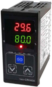
APOSUN CHCRH-400 Intelligent Temperature and Humidity Controller
Product Information
- Product Name: CHCRH Series intelligent temperature and humidity controller
- Description: This controller is designed to accurately measure and control temperature and humidity levels. It offers various control modes, input/output options, and alarm functions.
- Model: CHCRH-400
- Communication: RRS485
- Output Options: Relay, Solid State Relay (VSSR), Voltage
- Input Options: Voltage (0-3V), Digital Sensors (AM2305/AM2322B, SHT10), Thermocouple (K type), Platinum Resistance (PT100)
- Appearance: Size of 400x48x96mm or 72x72x96mm
- Working Voltage: 85-265VAC
- Working Environment: Temperature range of 0~50°C, humidity up to 85% RH without corrosion or condensation
Product Usage Instructions
- Read the user manual carefully before using the temperature and humidity controller.
- Ensure that the working voltage is within the specified range (85-265VAC) and the working environment meets the requirements (temperature range of 0~50°C, humidity up to 85% RH without corrosion or condensation).
- Choose the appropriate control mode based on your requirements:
- FF: heating/humidifying control mode
- Dd: cooling/pumping control mode
- Fd: heating/pumping control mode
- DF: cooling/humidifying control mode
- Set the temperature and humidity control target values using the SET button:
- Temperature Setting Range: CL-CH 0.0~99.9°C (Initial Value:30.0°C)
- Humidity Setting Range: 0.0~99.9% RH (Initial Value: 80.0% RH)
- Configure the input specifications for temperature and humidity:
- Temperature Input Specification: 0.0~50.0°C (Default: 1.0°C)
- Humidity Input Specification: Digital Sensor (AM2305/AM2322B, SHT10) or Voltage Signal (0-3V)
- Set the alarm values and modes:
- AL1 Alarm Value Range: 0.0~99.9
- AL2 Alarm Value Range: 0.0~99.9
- AL1 Alarm Mode: A (lower deviation alarm), B (upper deviation alarm), H (upper limit alarm), L (lower limit alarm), N (no alarm)
- AL2 Alarm Mode: A (lower deviation alarm), B (upper deviation alarm), H (upper limit alarm), L (lower limit alarm), N (no alarm)
- Adjust the lock parameters if needed:
- Lock Parameter Range: 0.0~99.9
- LCK=0: Field parameter values can be modified
- LCK=1: Field parameter values cannot be modified
- LCK=2-18: SV and field parameter values cannot be modified
- LCK=19: Enter engineering parameter group
- Perform temperature correction, humidity correction, and temperature alarm return if required.
Description and meaning of model

Instrument technical indicators
This instrument has the many kinds of temperature/humidity sensor signal input, the convenient user to select different types, and a variety of combination control mode (heating/humidification and cooling dehumidification, heating/dehumidification, cooling, humidifying) output, convenient to users. The two auxiliary outputs are freely defined as temperature or humidity assisted output. Multiple output options are available.
- Temperature/humidity display resolution: 0.1 or 1 optional.
- Temperature and humidity measurement accuracy:
K type thermocouple:±1 ℃; Pt100 platinum resistance:±0.5 ℃; NTC thermal resistor:±1 ℃ 0-3v senor: ±5%RH(10%-90%RH)/
AM2305:Humity ±2%RH(10%-90%RH)/Temp.±0.3℃
SHT10:Humity ±4.5%RH(10%-90%RH)/Temp.±0.5℃
AM2322B:Humity ±2%RH(10%-90%RH)/Temp.±0.3℃ - Control mode: ON/OFF switch control mode.
- Output of relay contact: AC250V/3A(drag) or AC250V/0.3A (inductive load)
- Drive solid state relay signal output: 12VDC/ 30mA.
- Working voltage: 85-265vac.
- working environment:0~50 ℃, temperature humidity <85% RH no corrosion, no condensation
- External dimensions (mm) : 48*96*96/72*72* 96; Installation opening: 45*92/68*68
Instrument panel and character description (example)


Instrument parameter description
(non-engineering technical personnel, do not change the engineering parameter value easily)
| Parameter name | characters | Ranges | initial value | Statement | |||
| Press the “SET” button briefly | |||||||
| Temperature setting | CL-CH | 30 .0 | Temperature control target (set value) | ||||
| Humidity setting value |  |
0 .0 ~99.9%RH | 80 .0 | Humidity control target value (set value) | |||
| Press the “SET” key for about 3 seconds to enter the field control parameter group setting | |||||||
| Control mode | 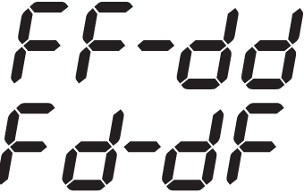 |
 |
FF: heating/humidifying control mode Dd: cooling/pumping control mode Fd: heating/pumping control mode DF: cooling/humidifying control mode | ||||
| Temperature control return |  |
0 .0 ~50.0 | 1 .0 | Temperature control return value | |||
| Temperature control return |  |
0 .0 ~50.0 | 1 .0 | Temperature control return value | |||
| Temperature input specification |  |
 |
 |
A:AM2305/AM2322B digital sensor S:SHT10 digital sensor N: 50K NTC thermal resistance K:K type thermocouple P: PT100 platinum resistance |
|||
| Humidity input specification |  |
 |
A:AM2305/AM2322B digital sensor S:SHT10 digital sensor V: 0-3v voltage signal humidity sensor |
||||
| Alarm object |  |
 |
Cr:AL1 is the temperature alarm, AL2 is the humidity alarm. C:AL1/AL2 is all temperature alarm. R: AL1/AL2 is all humidity alarm. |
||||
| AL1 alarm value | 
|
0 .0 ~99.9 | 5 .0 | AL 1alarm value | |||
| AL2 alarm value | 0 .0 ~99.9 | 5 .0 | AL 2alarm value | ||||
| AL1 alarm mode |  |
 |
A: lower deviation alarm. | ||||
| B:Upper deviation alarm | |||||||
| H: upper limit alarm | |||||||
| AL2 alarm mode |  |
 |
|||||
| L: lower limit alarm N: no alarm | |||||||
| Parameters of the lock |
0~19 | 0 | LCK=0: field parameter values can be modified. LCK=1: field parameter values cannot be modified. LCK=2-18:SV and field parameter values cannot be modified, LCK=19: enter engineering parameter group |
||||
| When LCK= 19, press the “SET” key to enter the engineering parameter group setting | |||||||
| Temperature correction |  |
– 20 .0 ~+50.0 | 0 .0 | Correction of measurement errors caused by temperature sensor problems | |||
| Humidity correction |  |
– 20 .0 ~+50.0 | 0 .0 | Correction of measurement errors caused by humidity sensor problems | |||
| Temperature alarm return |  |
0~+50.0 | 1.0 | Temperature alarm to cancel the return value | |||
| Humidity alarm return |  |
0~+50.0 | 1.0 | Humidity alarm to cancel the return value | |||
| Temperature value |  |
0~0.0 | 0 .0 | Temperature display and resolution | |||
| Humidity value |  |
0~0.0 | 0 .0 | Humidity display and set value resolution | |||
| Temperature limit |  |
0.0~99.9 | 0 .0 | Temperature as the minimum range value when the output is changed | |||
| Upper temperature display limit |  |
0.0~400.0 | 100.0 | Temperature as the maximum range value when the output is changed | |||
| Humidity display lower limit |  |
0.0~99.9 | 0 .0 | Humidity as the minimum range value when the output is changed | |||
| Humidity display upper limit |  |
0.0~99.9 | 100.0 | Humidity as the maximum range value when the output is changed | |||
| Temperature transmitting output |  |
0-20/4-20 | 4-20 | The temperature current (mA) changes delivery specification | |||
| Humidity transmitting output |  |
0-20/4-20 | 4-20 | Humidity current (mA) change delivery specification | |||
| Minimum temperature setting range |  |
-20.0~100.0 | 0 | The limit temperature SV set the minimum value | |||
| Maximum temperature setting range |  |
– 2 0~400.0 | 99.9 | The limit temperature SV set the maximum value | |||
| Correspondence address |  |
0~80 | 1 | Set up the instrument communication address | |||

Precautions for use and order
- The type and specification of the input signal of the instrument before use, and the requirements of the installation control system shall be met in accordance with the requirements of the installation control system.
- Please contact the distributor or manufacturer according to the correct wiring drawings or instructions.
- K type thermocouple, if you want to extend the sensor lead, please use thermocouple compensation wire, using internal automatic compensation models, compensation conductor should be directly to the instrument of the terminal, middle can’t into conventional wire, otherwise it will produce error of measurement.
- When receiving the Pt100 platinum resistance, when using the compensation wire, please use the same specification of low resistance wire, and the three-wire resistance value is as much as possible to avoid measurement errors.
- If the instrument sensor is connected to the wrong line or the input signal is abnormal, the digital tube will display the fault code Err. Is the sensor damaged?
- The instrument power line and the signal line should be separated from the large current transmission line to reduce the influence of the electromagnetic radiation on the instrument. In case of unavoidable, please use the shielded wire as far as possible.
- The instrument can be energized only when the wiring is correct, especially the power supply and output power line, which may damage the internal circuit of the instrument.
- when ordering, please specify the instrument specific models (see the instruction of “model meaning and expression” column) can also be note details of instrument input signal types, specifications, measuring range, output method, instrument power supply or other special technical requirements.
- Accessories attached to the factory instrument: a set of mounting bracket, one copy, and one set of temperature and humidity sensors. If there is any abnormality in the use of instrument, please check the instruction manual or the after-sales service hot-line email:cynthia-leung@qq.com for technical support
- During the use of failure and unsealed, the manufacturer shall maintain free maintenance within one year.
Procedure diagram of instrument parameter setting


Instrument wiring reference diagram


Documents / Resources
 |
APOSUN CHCRH-400 Intelligent Temperature and Humidity Controller [pdf] Instruction Manual CHCRH-400 Intelligent Temperature and Humidity Controller, CHCRH-400, Intelligent Temperature and Humidity Controller, Temperature and Humidity Controller, Humidity Controller, Controller |


