APLISENS APC-2000ALM Smart Pressure Transmitter
Specifications
- Product Name: SMART PRESSURE TRANSMITTER APC-2000ALM
- Manufacturer: APLISENS S.A.
- Model Numbers: APC-2000ALM, APR-2000ALM, APR-2000ALM/G, APR-2000YALW
- Contact: Morelowa 7 St, 03-192 Warsaw
- Phone: +48 22 814 07 77
- Fax: +48 22 814 07 78
- Email: export@aplisens.com
- Website: www.aplisens.com
EXPLOSION-PROOF DEVICE MANUAL
SMART PRESSURE TRANSMITTER
APC-2000ALM
SMART PRESSURE DIFFERENTIAL TRANSMITTERS APR-2000ALM, APR-2000ALM/G
SMART LEVEL PROBE
APR-2000YALW
Symbols used
Symbol Description
 Warning about the necessity follow strictly the information provided in the documentation in order to ensure safety and full functionality of the device.
 Information particularly useful for device installation and operation.
 Information particularly useful for Ex device installation and operation.
 Waste of electrical and electronic equipment disposal information.
BASIC REQUIREMENTS AND OPERATION SAFETY
- The manufacturer shall not be liable for any damage resulting from incorrect installation, failure to maintain the device in proper condition, or device use other than intended.
- Installation should be carried out by qualified staff having the required authorization to install electrical and I&C equipment. The fitter is responsible for performing the installation in accordance with this manual and with the electromagnetic compatibility and safety regulations and standards applicable to the type of installation.
- If leakage in systems with I&C equipment occurs, pressurized medium poses a threat to the personnel. All safety and protection requirements must be observed during transmitter installation, operation and inspections.
- If a malfunction occurs, the device should be removed and sent for repair to the manufacturer or a facility authorized by the manufacturer.
In order to minimize the risk of malfunction and associated risks to staff, do not install or use the device in particularly adverse conditions, where the following hazards occur:
- Possible mechanical impacts, excessive shocks and vibration;
- Excessive temperature fluctuation;
- Water condensation, dust, icing.
Explosion-proof installations should be made with special care and in accordance with standards and regulations applicable to this type of installations.
Changes can be made in the manufacturing before the paper version of the manual is updated. The up-to-date user manuals are available on the manufacturer’s website: www.aplisens.com.
INTRODUCTION
This manual is only applicable to the APC-2000ALM, APR–2000ALM, APR–2000ALM, APR-2000ALM/G series transmitters in Ex (explosion-proof): Exd (flameproof). The transmitters are identified with model ID on nameplates and also as specified in section 4. Ex information are included in the “Product Certificate”. Model ID indicates type and version of transmitter. The manual contains most important information about intrinsically safe and flameproof transmitters compliant with ATEX directive and IECEx requirements. During installation and use of explosion-proof transmitters, refer to this manual and also EN.IO.APC.APR.ALM manual.
SAFETY
- Read this manual carefully before installing, commissioning and operating the transmitter.
- Installation and maintenance should be carried out by qualified staff having the required authorization to install electrical and measuring devices.
- The transmitter should be used as intended within permissible parameters.
- Power source must be disconnected before installing or removing the transmitter.
- No repairs or alterations to the transducer electronic system are permitted. Only the manufacturer or a facility authorized by the manufacturer may assess damages and repair the device (if possible).
- Do not use damaged instruments. In case of failure, the device must be disconnected.
- If the equipment is used in Ex zones, the technical requirements specified in this manual and applicable local (national) regulations must be followed.
COMPLETE DELIVERY CHECKLIST
The user receives the following with the transmitter:
- product Certificate, which also constitutes a warranty card.
- declaration of conformity.
- certificate copy (on request).
- EN.IX.APC.APR.ALM explosion-proof device manual.
- EN.IO.APC.APR.ALM user manual.
Items b), c), d), e) are available at www.aplisens.com.
IDENTIFICATION MARKS.
Ex transmitters are delivered with a nameplate which contains data specified in EN.IO.APC.APR.ALM and also the following:
- designation of explosion-proof design type, certificate number.
- year of manufacture.
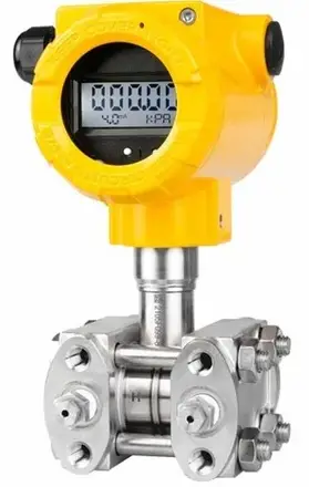
TRANSMITTER DESIGN
The basic transmitter components are: an housing made of 316 (1.4401) stainless steel or aluminum, measuring head where a pressure signal is converted to an electrical signal, and an electronic module converting the signal from the head to an output signal. Transmitters in aluminum housings are allowed for II and III group, and transmitters in steel housings are allowed for I, II and III group.
ELECTROSTATIC HAZARDS
The paint, plastic nameplate and diaphragm seals coated with PTFE form a non-conducting layer applied on a conducting base of housing or diaphragm seals. Transmitters with this design in a dust-explosion zone should be installed in a place where electrostatic charging is impossible, in particular by contact with electrically charged dust falling off or blown from neighboring devices.
SPECIAL CONDITIONS OF USE
- In hazardous zones of dust explosion, transmitters with painted housings, as well as transmitters equipped with plastic nameplates and diaphragm separator elements covered PTFE layer, should be installed in places and in a way that prevents electrostatic charging, in accordance with the instructions.
- The diaphragm separator containing titanium elements must be protected against mechanical impacts.
- The diaphragm in contact with the medium must not be exposed to an environment that could damage it.
- Power supply of the transmitters should be compliant with the overvoltage category II (or better) in accordance with EN 60664-1 standard.
- Flameproof joints are not intended for repair.
TRANSMITTER PROTECTION LEVEL (EPL) AND HAZARDOUS AREAS
Ga/Gb (Da/Db) EPL protection level means that the transmitter can be installed in Zone 1 or 2, and transmitter process connections can connect to Zone 0. EPL Db protection level means that the transmitter and process connection can be installed in Zone 21 or 22 Transmitters for mining applications Mb should be turned off if explosion hazard occurs.

FLAMEPROOF Exd TRANSMITTERS ACCORDING TO CERTIFICATES JSHP 24 ATEX 0040X and IECEx JSH 24.0009X
Approvals
The transmitters are ATEX and IECEX certified, which is confirmed by type examination certificates.
Standards used for assessment
The transmitters are manufactured in compliance with the following standards:
- EN 60079-0:2018 (IEC 60079-0:2017 ed. 7.0)
- EN 60079-11:2012 (IEC 60079-11:2011 ed. 6.0)
- EN 60079-1:2014 (IEC 60079-1:2014 ed. 7.0)
- EN 60079-31:2014
- IEC 60079-31:2022 ed. 3.0
- EN 60079-26:2015 (IEC 60079-26:2014 ed. 3.0)
Transmitters explosion-proof (Exd) designations according to certificates JSHP 24 ATEX 0040X and IECEx JSH 24.0009X
The following ATEX and IECEx markings apply only to flameproof transmitters marked with the type:
 ATEX
ATEX
- II 1/2G Ex ia/db IIC T5 Ga/Gb
- II 2G Ex db ia IIC T5 Gb (for the APR-2000ALW/G)
- II 2D Ex ia/tb IIIC T100ºC Db
- I M2 Ex db ia I Mb (for the version with 316 steel housing)
- JSHP 24 ATEX 0040X
IECEx:
Ex ia/db IIC T5 Ga/Gb
Ex db ia IIC T5 Gb (for the APR-2000ALW/G)
Ex ia/tb IIIC T100ºC Db
Ex db ia I Mb (for the version with 316 steel housing)
IECEx JSH 24.0009X
PERMISSIBLE PARAMETERS OF Exd TRANSMITTERS
Ambient temperature range and temperature classes
Table 1. Ambient temperature range and temperature classes for Exd transmitters
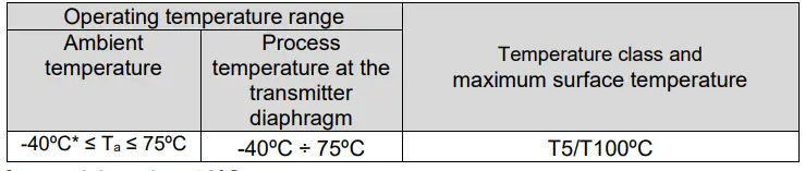
*) for special version -50ºC
If the medium temperature can exceed Tamax, separating elements, such as diaphragm separators, siphon tubes, etc., should be used. The transmitter operating temperature Tp must meet the Tp≤Tamax condition.
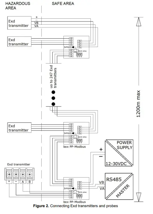
Power supply, connection and operation of Exd transmitters
Connect the transmitter according to the electrical diagram (Figure 2). The transmitter electrical connections in potentially explosive zones should be made by personnel having necessary knowledge and experience in this area. The transmitters should be properly grounded by means of a grounding terminal. If the transmitter has metal contact with grounding structural elements or piping, separate transmitter grounding is not necessary.
Transmitter and equipment in the transmitter measurement loop must be connected in compliance with explosion-proof standards and conditions for application in explosion risk zones. If these rules are not followed, explosion can occur and people can be exposed to danger.
Termination resistor 120 Ω, which is by default included in the transmission system using a jumper between „Digital” terminals A and B (Aplisens PP Modbus boxes are factory equipped with resistor 120 Ω), should be used at all transmission speeds (especially @1152200 bps).
Termination resistor 120 Ω, which is by default included in the transmission system using a jumper between „Digital” terminals A and B (Aplisens PP Modbus boxes are factory equipped with resistor 120 Ω), should be used at all transmission speeds (especially @1152200 bps).
Table 2. Maximum supply voltage for Exd transmitters

In an explosion risk zone, do not remove the cover of supplied transmitter and do not connect to the terminals, and do not change the position of local indicator (display).
In order to secure the side covers against loosening, unscrew the hex socket screws pressing the screw heads against the edges of the covers. The method of locking the covers against unscrewing and the possible method of sealing the transmitter are presented in figure below. 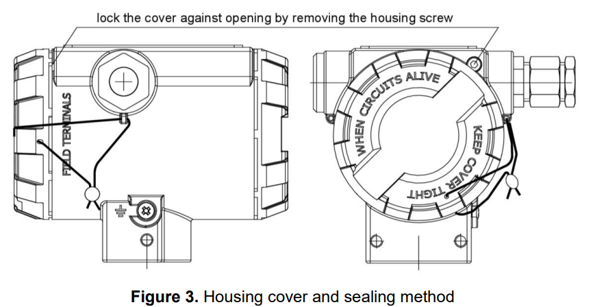
No repairs or alterations to the transmitter housing elements and electrical system are permitted. Repairs on flameproof joints are not permitted. Only the manufacturer or a facility authorized by the manufacturer may assess damages and repair the device (if possible).
Due to the type of housing material (light alloy with high aluminum content), the user is obliged to ensure that in the transmitter installation site its housing cannot be hit and, consequently, damaged.
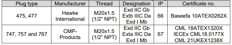
In a transmitter housing there are two holes for installing, one for a cable entry and second for a blinding plug with M20x1.5 or 1/2 NPT thread. As standard, the transmitter is delivered to the customer without cable gland installed. After consultation with the manufacturer, the user can purchase a transmitter with a cable gland, or without a cable gland and the missing cable gland purchase separately. A transport plug is installed in the cable gland place. In such case, the transport plug should be removed and appropriate cable gland installed (Figure 4) before the transmitter is installed. It is responsibility of the user to install a certified cable gland compliant with the list of equivalent cable glands presented in Table 3. List of equivalent cable entries. As a blinding plug, an Aplisens plug supplied with the transmitter or a certified blinding plug compliant with the list of equivalent blinding plugs in Table 4 can be used. It is allowed to install other types of certified cable entries and blinding plugs about marking Exd IIC Gb, Extb IIIC Db and Exd I Mb with at least IP66 protection and -40°C…75°C temperature range.
Apply LOCTITE 577 on the 1/2 NPT thread of cable gland before installation. When connecting, make sure that the cable type and diameter is suitable for the cable gland used and temperature in the installation site.
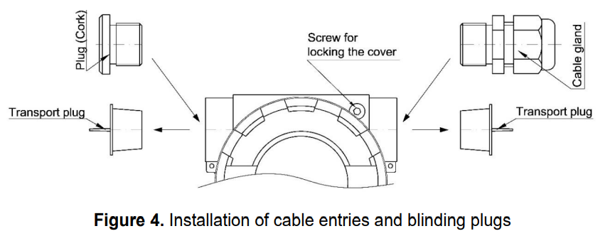
Table 3. List of equivalent cable entries
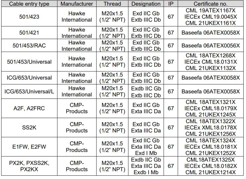
Table 4. List of equivalent blinding plugs
Use a shielded or unshielded, non-reinforced cable with compact structure and circular cross-section in an non-hygroscopic sheath made of an elastomer, e.g. YKSLY 2*1, YnTKSYekw 1*2*1, LIYCY 2*1.
If a cable of different design has to be used, it should be agreed on with the transmitter manufacturer in order to choose a suitable cable gland or individually purchase a cable gland suited to the cable used. The list of equivalent cable entries is given above (Table 3). The cables should be protected from damage by routing them in cable trays, jacket tubes, cable ladders, by using fixed mounts, etc.
When periodic inspections are performed, the covers tightness, cable entry and cable fixing in the cable entry should be checked. Visually check the housing and cable for mechanical damage, and the nameplate for legibility. The sensor diaphragm should be also included to periodic inspections. There shouldn’t be a signs of damage. During maintenance it is recommended to apply acid-free petroleum jelly on threads connection.
The diaphragm should not be exposed to damage during transmitter installation and operation. The transmitter diaphragm is made of stainless steel or Hastelloy and must not be exposed to contact with a medium that may damage it.
The connecting and operating general rules for an Exd transmitters should be compliant with the rules and standards applicable to devices in a flameproof housing: EN 60079-14 – Electrical devices in explosive atmospheres. Part 14: Electrical installations in risk areas (other than mines).
EN 60079-17 – Electrical devices in explosive atmospheres. Part 17: Electrical installations inspection and maintenance in risk areas (other than mines).
Due to possible damage, the transmitter should be protected from heating above 80ºC also when explosion hazard does not occur.
ADDITIONAL INFORMATION
Additional information
The manufacturer reserves the right to introduce structural and technological changes to the device, which does not deteriorate its performance.
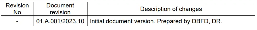
History of revisions
FAQ
- Q: Where can I find the most up-to-date user manuals?
A: The latest user manuals are available on the manufacturer’s website at www.aplisens.com. - Q: What should I do to ensure the safety of device operation?
A: Follow the instructions provided in the documentation strictly and avoid using the device in adverse conditions as outlined in the manual.
Documents / Resources
 |
APLISENS APC-2000ALM Smart Pressure Transmitter [pdf] Owner's Manual APC-2000ALM, APR-2000ALM, APR-2000ALM-G, APR-2000YALW, APC-2000ALM Smart Pressure Transmitter, APC-2000ALM, Smart Pressure Transmitter, Pressure Transmitter, Transmitter |


