APG CR-L Radar Liquid Level Sensor

INTRODUCTION
Thank you for purchasing a TRUE ECHO® CR-L Radar Liquid Level Sensor from APG. We appreciate your business! Please take a few minutes to familiarize yourself with your sensor and this manual.
The TRUE ECHO CR-L radar is a Frequency Modulated Continuous Wave (FMCW) radar operating at 76-81 GHz. It has a maximum measuring range of 49.2 feet (15 m) and a minimum blind zone of 7.87 inches (0.2 m). The TRUE ECHO CR-L brings the accurate level readings of radar sensors to industrial liquid measurements. It can accurately measure in many adverse environments. Its narrow beam can detect small targets and achieve precise positioning with high resolution. All TRUE ECHO CR-L sensors can be easily setup and field adjusted via the TRUE ECHO Bluetooth app.
NOTE: Find product specifications, accessories, and more in the Data Sheet. Go to: https://www.apgsensors.com/wp-content/uploads/2024/06/TRUE-ECHO-CR-L-spec-sheet.pdf
Reading your label
Every TRUE ECHO sensor comes with a label that includes the instrument’s part number, model number, and serial number. Please ensure that the part number on your label matches your order.
Key Features
- Accurate level measurements in various adverse environmental conditions.
- Millimeter wave technology allows higher signal-to-noise ratio and smaller blind zone.
- The 4° antenna beam half angle means the environmental interference has less impact on the sensor and the installation is more convenient.
- Integrated design, small size.
- Chemical resistance
- 4-20mA (2 wire), and RS-485 (4 wire) outputs.
- Bluetooth communication to facilitate on-site personnel maintenance work.
IMPORTANT: FCC regulations require 75-85 GHz radars to be installed to ensure a vertically downward orientation at fixed locations only. They must not operate while being moved or while inside a moving container. Hand-held applications are prohibited as well as marketing to residential consumers.
WARRANTY AND WARRANTY RESTRICTIONS
This product is covered by APG’s warranty to be free from defects in material and workmanship under normal use and service of the product for 24 months. For a full explanation of our Warranty, please visit https://www.apgsensors.com/resources/warranty-certifications/warranty-returns/. Contact Technical Support to receive a Return Material Authorization before shipping your product back.
Repair and Returns
Should your TRUE ECHO Radar require service, please contact the factory via phone, email, or online chat. We will issue you a Return Material Authorization (RMA) number with instructions. You can also find the form on our website by clicking “RMA” in the web footer, or go to https://share.hsforms.com/1rPTIAWbsTMiD0XD_SkBs6g2rio0.
- Phone: 888-525-7300
- Email: sales@apgsensors.com
- Online chat at www.apgsensors.com
Please have your part number and serial number available.
DIMENSIONS AND WIRING
Dimensions

Electrical Pinout and Power Supply Tables
- Pin Out Tables

Wiring Information
- Power Supply Table

INSTALLATION AND REMOVAL PROCEDURES
Physical Installation Notes
- The material to be measured must have a dielectric constant greater than 2.
- In areas with direct sunlight, it is recommended to install the instrument in a cool place or use a sun visor to avoid excessive temperature and to provide good ventilation and heat dissipation.
- Mount your TRUE ECHO sensor so that it has a clear, perpendicular path to the surface being monitored.
- Install at least 8 inches from a side wall.
- The radar path should be free from obstructions and as open as possible for the 4° off axis beam pattern. Mount the sensor away from tank or vessel inlets.
- Wrap PTFE tape around threads before installing the radar into the tank opening. This will help it screw in easier. Do not over tighten.
- Be careful not to scratch or damage the radar face.
Tools Needed
- Tools to make electrical connection
- Mobile device with Bluetooth
Tools Needed
- STEP 1: Mount the radar using the 2 inch NPT bottom threads or the 3/4 inch NPT top threads and nut. Do not over tighten.
- STEP 2: Attach the wires to your control system according to the Wire Diagrams on page 2.
- STEP 3: Power on the radar.
- STEP 4: Use the TRUE ECHO app to connect to the radar via Bluetooth. See “Programming with the App” on page 6 for more information.
NOTE: Do NOT suspend radar by cable.
Sensor Placement
Ensure the radar level transmitter is installed perpendicular to the liquid surface. Installing the radar at an angle will weaken the signal amplitude, cause unwanted reflections, and affect the normal range.
Ensure that there are no interferences within the beam angle, such as a river bank, tank wall, ladders, steps, etc.
Install the radar at least 7.9 inch (20 cm) away from side walls. When installing in wells or pipes, place the radar as close to the center as possible to avoid interference from the walls.
When installing in tanks with domed lids, install off center to avoid additional false echoes.
Removal Instructions
Removing your radar from service must be done with care.
- STEP 1: Ensure power is turned off. If the radar was installed in a hazardous location, ensure that the cables will not energize while the sensor is disconnected.
- STEP 2: Disconnect the radar wires.
- STEP 3: Remove the radar from its mount.
- STEP 4: Store it in a dry place, at a temperature between -40° to 158°F (-40° to 70°C).
PROGRAMMING WITH THE APP
All TRUE ECHO radar sensors are Bluetooth-compatible. To change settings and parameters easily with your mobile device, download the free TRUE ECHO Radar App by searching “TRUE ECHO” in the Apple or Google Play Store.
Connect Bluetooth
- STEP 1: Install the TRUE ECHO app from the app store.
- STEP 2: Turn on your mobile device’s Bluetooth.
- STEP 3: Open the TRUE ECHO app. On the Select Device screen, press “General Purpose Radar.”
- STEP 4: Press the “Set up” button next to the radar’s name.
- STEP 5: Press “Read” to view current settings in each tab. Press “Write” to save changes.
- STEP 6: The Distance, Level, and mA readings (for 4-20mA units only) appear in a banner along the bottom of the screen.

NOTE: If you don’t see the device on the scanning screen, make sure the radar is wired correctly and powered on. Press “Refresh” to scan for devices.
Programming Quick Start
- STEP 1: Validate the Media Type is set to liquid. The CR-L General Purpose Radar is typically used for liquid level applications.
- STEP 2: Choose a Vessel Type in the BASIC tab. This setting selects defaults to optimize performance.
- STEP 3: Press “Write” to confirm your choice. Press “Read” to view new settings.
- STEP 4: Set the Low Level, High Level, and Range settings. The Range setting should be equal to the Low Level setting to optimize performance.
- STEP 5: Press “Write” to confirm your choice. Press “Read” to view settings.
- STEP 6: Press the ECHO tab to view the echo waveform graph.
- STEP 7: In the case of obstructions, use the False Echo Begin and False Echo End settings in the ADVANCED tab to create a false echo mask.
- STEP 8: Press “Write” to confirm your choice. Press “Read” to view settings.
- STEP 9: Validate the performance of the radar in the ECHO tab.
UNIT SELECT
The UNIT SELECT tab is located on the left panel below the ECHO tab. The options are:
- Meters (m)
- Feet (ft)
- Inches (in)
BLE NAME
The BLE NAME tab is located on the left panel, below the UNIT SELECT tab. This allows you to change your unit’s Bluetooth name.
BASIC Tab
- Low Level
Low Level is the furthest point to be measured from the sensor’s reference point. For the 4-20mA sensor, the Low Level sets the 4mA setpoint, depending on the Output Mode (see pg 13). Set the Low Level to the lowest point in the tank.- Range: 0.656 to 49.213 ft (0.2 to 15 m)
- Default: 49.213 ft (15 m)
Low Level must be less than or equal to the sensor range.
- High Level
High Level is the closest point to be measured from the sensor’s reference point. For the 4-20mA sensors, the High Level sets the 20mA setpoint, depending on the Output mode. Set the High Level value to the max fill point in the tank.- Range: 0 to 48.88 ft (0 to 14.9 m)
- Default: 0 ft
The High Level value must be less than the Low Level value.
- Range
Range defines the maximum distance the sensor will look for a target. Typically, Range is set at or a little beyond the desired measuring range to avoid false echoes and achieve a fast and stable measurement.- Range: 0.656 to 49.213 ft (0.2 to 15 m)
- Default: 49.213 ft (15 m)
- Blind Zone
Blind Zone defines the area in front of the sensor that will not be seen as a valid target. Typically, Blind Zone is set at or near the top or the desired measuring range to achieve a fast and stable measurement.- Range: 0 to 49.213 ft (0 to 15 m)
- Default: 0 ft
NOTE: The Blind Zone and Range determine the processing bounds of the application. They should be set to avoid interference and false echoes and to achieve a fast and stable measurement.
- Damping
Damping is a filter used to smooth sudden changes in the measurement results. A longer Damping time will provide more smoothing for sudden changes. A shorter Damping time will provide faster outputs. Damping default values are set by the Vessel Type setting based on expected level change rates.- Range: 0 to 100 seconds
- Default: Set by vessel type
- The time from radar power-on to the actual position is given by the following equations:
- RS-485 Radar: Damping x 4.5 + 7 seconds
- 4-20mA Radar: Damping x 4 + 7 seconds
- After power-on, time from actual level change to measured level output is given by:
- RS-485 Radar: Damping x 4.5 seconds
- 4-20mA Radar: Damping x 4 seconds
For Example: If the Damping time for a RS-485 radar is set to 5 seconds and the position of the measured object changes by a step at time t, the measured output value will follow to the actual position of the measured object after approximately 22.5 seconds.
- Media Type
Media Type affects the selection of the echo algorithm used for Liquids and Solids. The CR-L TRUE ECHO General Purpose Radar is designed to measure liquids. The options are:
- Liquid (default)
- Solid (not recommended)
- Vessel Type
Vessel Type is used to automatically setup damping and other parameters based on how fast the liquid level is expected to change in various tank sizes. The options are:
- Big
- Small (default)
- Fast
- Test
Selecting the correct Vessel Type is important to properly programming your radar.
For best results, change the Vessel Type setting, then immediately press “Write” to confirm. Press “Read” to view the new settings.
ADVANCED Tab
- False Echo Begin and End
False Echo Begin and False Echo End settings are used to manually mask out unwanted false echoes, usually caused by obstacles in the container. Set the False Echo Begin value to before the false echo. Set the False Echo End value to after the false echo.
- Range: 0 to 49.213 ft (0 to 15 m)
- Default: 0 (no masks)
In the example below (Figure 3.11), there is an obstacle at 3 meters. False Echo Begin is set to 2 meters and the False Echo End is set to 4 meters.
Multiple false echoes masks can be applied. To delete all masks, enter 0 into both of the False Echo Begin and False Echo End fields. Press “Write” to confirm.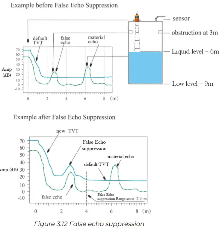
NOTE: TVT means “Time Varying Threshold.” The threshold curve will exclude background noise and mask false echoes.
- False Echo Intensity
False Echo Intensity is the intensity of the false echo you want to mask out in decibels (dB). The algorithm adds the value in dB to the obstacle to be masked out. In most cases this setting does not need to be changed.- Range: 0 to 170 dB
- Default: 18 dB
- Distance Offset
Distance Offset positions the zero reference point of the sensor to be at the bottom of the NPT threads as indicated by point A in Figure 3.12. It can also be used to offset the sensor reference point as needed.
- Range: -32.808 to 32.808 ft (-10 to 10 m)
- Default: Calibrated at factory
To adjust the reference point to point B, enter the distance between points A and B as a negative value. If A is -0.197 and desired reference point B is 1 foot in front of the face, enter -1.197 ft.
To adjust the reference point to point C, enter the distance between points A and B as a positive value. If A is -0.197 and desired reference point C is 1 foot behind the face, enter 0.803 ft.
- Bus Address
Bus Address can be changed when two or more RS-485 Modbus instruments are connected. The default Bus Address is 1. Address the higher numbered instruments first before adding them to the bus.
See the Modbus Programming section on page 15 for more information about RS-485 programming. - Output Mode
Output Mode changes the output from 4-20mA to 20-4mA. It corresponds to the Low Level and High Level values as shown in the table below. The options are:
- 4-20mA (Default)
- 20-4mA

- 4-20mA Current Test
4-20mA Current Test is not currently used for the TRUE ECHO General Purpose Radar. - Loss of Echo Output
Loss of Echo Output allows the user to set the 4-20mA value when the unit encounters a loss of echo error. “Unchanged” holds the value of the last valid echo. The options are:
- Unchanged (Default)
- 22mA
- 3.6mA
SERVICE and FACTORY Tabs
The SERVICE and FACTORY tabs are primarily used to set parameters by the factory. A password is required to read or write these settings in the app. For unique applications that require additional radar tuning, please contact APG for help setting up these parameters.
ECHO Tab
The ECHO Tab opens the echo waveform graph with the current distance (D:) and level (L:) measurement. The displayed mA value is only applicable to 4-20mA sensors. The horizontal axis is distance from the sensor face and the vertical axis is the echo strength in decibels (dB). It may take a few moments for the graph to load. The graph shows the echo curve (blue line), threshold curve (red line), and current position (green line). Tap anywhere on the graph to show the threshold and echo curve pinpoint box. This can be used to determine the location of false echoes for the purpose of masking them out.

TIP: Tap the top of the popup banner to close the popup. Do not press the back arrow on your device.
MODBUS PROGRAMMING
RS-485 (4-Wire) Units Only
TRUE ECHO Radar sensors use standard RS-485 Modbus RTU protocol. The sensors can only operate as client devices. Sensor default transmission settings are 9600 Baud, 8 Bits, 1 Stop Bit, No Parity, and require a minimum delay of 100 ms between transactions.
For explanations about specific settings, go to Chapter 3: Programming with the App.
Modbus communication may override Bluetooth communication. Using both simultaneously may result in slower app response times.
Reading Registers (Function Code 0x03)

Read Holding Registers (Function Code 0x03)

APPLICATION EXAMPLES
Water Tank Level Management
- Tank Height: 10 ft
- Sensor Placement (Range): Zero reference is 10.5 ft above tank bottom
- Max Water Height Measured (High Level): 1.5 ft from zero reference
- Min Water Height Measured (Low Level): 10.5 ft from zero reference
- Loss of Echo Output: 22mA


Flowing Water Level Management
- Sensor Zero Reference to Ground: 10 ft
- Max Water Height Measured (High Level): 4 ft from zero reference
- Min Water Height Measured (Low Level): 9.5 ft from zero reference
- Loss of Echo Output: 3.6mA


MAINTENANCE
General Care
Your radar is very low maintenance and will need little care as long as it is installed correctly. However, in general, you should:
- Avoid applications for which the sensor was not designed, such as extreme temperatures, contact with incompatible corrosive chemicals, or other damaging environments.
- Inspect the threads whenever you remove the sensor from duty or change its location.
SETTING DEFAULTS

BEAM ANGLE REFERENCE TABLE
The CR-L General Purpose Radar has a 4° half angle beam. The diameter of the measuring spot can be calculated using:

Automation Products Group, Inc.
Tel: 1 888-525-7300 or 1 435-753-7300
e-mail: sales@apgsensors.com
www.apgsensors.com
Automation Products Group, Inc.
1025 W. 1700 N.
Logan, UT 84321
Documents / Resources
 |
APG CR-L Radar Liquid Level Sensor [pdf] User Manual CR-L Radar Liquid Level Sensor, CR-L, Radar Liquid Level Sensor, Liquid Level Sensor, Level Sensor, Sensor |