AMplitec C20L Triple Band Consumer Repeater User Manual

PLEASE KEEP APPROPRIATELY AND CAREFULLY READ THIS USER MANUAL BEFORE INSTALLATION
 The power supply voltage of repeater should meet the standards of security requirements.
 The repeater should be installed and started by professionals.
- Keep the repeater away from heat source, do not install in a narrow space
- Ensure of grounding, waterproof and lightning protection when installing the repeater .
 Do not dismantle the repeater for repair or replacement of components.
PACKAGE CONTENT
- C20L Signal Repeater 1pc
- 12V/3A Power Adapter 1 set

- Installation Screws 1pack

PRODUCT DESCRIPTION
C20L triple band series is an intelligent mobile phone signal repeater, It adopts digital AL C and anti-interference technology, which can detect the signal quality in the coverage area in real time and auto adjust the working status accordingly. The signal repeater can automatically attenuate the gain of uplink and downlink according to the detected signal intensity so as to maintain the link balance; when there is insufficient isolation between indoor and outdoor antennas ,it will automatically decrease gain to eliminate self-oscillation; and when there is no user in the coverage area, the device will automatically shut off uplink to lower the power consumption and decrease the interference to the base station.
C20L triple band series support three different systems, It can amplify 2G, 3G, 4Gor 5Gsignals in local several operator’s network by selecting suitable model. With features like elegant appearance, compact size and easy to install and maintain, the coveragecanbeupto600 square meters when it is properly installed, it’s the best choice to solve week signal problems in the house, office, elevator and basement etc.
PRODUCT FEATURES
- LCD screen to display device’s operating parameters clearly, button control to make it easier to operate;
- Able to support several mobile operators’ networks;
- Low power consumption, low interference;
- Manual gain control, with 1dB step to attenuate the gain among the range of 1-31dB;
- Digital ALC technology, auto controlling the output power to ensure stable signal coverage;
- Anti interference technology, auto detecting real time isolation. When isolation is insufficient, the device will auto attenuating the gain, to prevent self-oscillation occurring to interfering the base station;
- Uplink dormant function, when no mobile user is in the coverage area, device will shut off up link output, to lower the power consumption and not to interfere the base station;
- Downlink shut off function, when the repeater is self-oscillating or overloaded, the device will shut off; and after self-oscillation and overload is eliminated, device will automatically return to work.
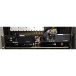
CONNECTOR DESCRIPTION

- A :Outdoor antenna connection port(N-Female)
- B :Indoor antenna connection port(N-female)
- C :12V DC power connection port
- D :Power switch
- E :Grounding screws
- F :To value decrease button
- G :To value increase button
- H :To select and confirm button
- I :LCD display screen
- J :Alarm indicator
- K :Working status indicator
OPERATION AND DISPLAY DESCRIPTION
Buttons on the Control Panel
- INC+:To increase the value
- DEC-:To decrease the value
- SET: To select and confirm the operation
Screen and Display
After power-on, the device will display the working frequency(The frequencies in the following operation are for reference only and the real working frequency will be matching the equipment in use.), downlink and uplink gain, downlink output power, and isolation and ALCalarm. (figure 1)

figure 1
Frequency Checking and Setting
Press “SET” button till “Band 5:850 MHz” flashing, then press “INC+” or “DEC” to change working frequency, press “SET” button to exit.( figures 2 and 3)

figure 2

figure 3
Output Power Checking
Press “SET” button, “pout” lights, then the real-time downlink output power will be displayed on the right side of the screen.(figure 4)

figure 4
Gain Checking and Gain Attenuation Setting
Just follow step “Ⅲ” to select the frequency you want, and then press “SET” button, when “Gain UL” lights, the real time uplink gain will be displayed on the right of screen(figure5),and then press “INC+”or “DEC-” button to adjust the uplink gain(figure 6); press “SET” button, “GainDL” lights, the real-time downlink gain will be displayed on the right of screen(figure7), and then press “INC+” or “DEC-” to adjust the downlink gain(figure 8)

figure 5

figure 6

figure 7

figure 8
Uplink Auto Shutoff Function
When uplink signal input is less than -80dBm ( or there is no mobile user in the coverage area), uplink automatically shut off, “Work” in the left lower of the screen will go out and “RUN” LED starts flashing(figure 9), when uplink signal input is less than -75dBm, the uplink starts to work and “RUN” LED lights.(as figure 10).

figure 9

figure 10
Self-oscillation Elimination and Auto Shutoff Function
The device will automatically detect the real time isolation. When there is insufficient isolation between outdoor and indoor antennas, with “I.S.O” lighting(figure 11) ,the device will automatically attenuate its gain to make it work normally; when the isolation of outdoor and indoor antenna is less than 55dB and over, the device will self-oscillate seriously, with “I.S.O ”flashing (figure 12), the device will automatically shutoff to prevent self-oscillation from interfering the base station. In this case, turn this device off, adjust antenna orientation and height until the isolation is greater than 85dB, and then turn the power back on.

figure 11

figure 12
TECHNICAL SPECIFICATION
| Items | Uplink | Downlink | |||
| Model/ Frequency Range | C20L-B1B3B5 | 824~849/1710~1785/1920~1980 | 869~894/1805~1880/2110~2170 | ||
| C20L-B1B3B8 | 880~915/1710~1785/1920~1980 | 925~960/1805~1880/2110~2170 | |||
| C20L-B2B4B5 | 824~849/1850~1910/1710~1755 | 869~894/1930~1990/2110~2155 | |||
| C20L-B3B7B8 | 880~915/1710~1785/2500~2570 | 925~960/1805~1880/2620~2690 | |||
| C20L-B3B8B20 | 832~862/880~915/1710~1785 | 791~821/925~960/1805~1880 | |||
| C20L-B1B3B7 | 1710~1785/1920~1980/2500~2570 | 1805~1880/2110~2170/2620~2690 | |||
| C20L-B1B8B28A(B) | 03~733(718~748)/880~915/ 1920~1980 | 758~788(773~803)/925~960/ 2110~2170 | |||
| C20L-B1B3B20 | 832~862/1710~1785/1920~1980 | 791~821/1805~1880/2110~2170 | |||
| Gain | 65±3 dB | 70±3 dB | |||
| Ripple in Band | 6 ~ 15 dB | ||||
| VSWR | ≤2.5 | ≤2.5 | |||
| Output Power | 15±2 dBm | 20±2 dBm | |||
| ALC Adjustable Range | 31 dB | 31dB | |||
| Max Input Power Without Damage | 0 dBm | 0 dBm | |||
| Inter-modulation Products(CW) | ≤-40 dBc | ≤-40 dBc | |||
| Spurious Emission | 9KHz~1GHz | ≤-36 dBm | ≤-36 dBm | ||
| 1GHz~12.75GHz | ≤-30 dBm | ≤-30 dBm | |||
| MGC(ATT)Gain Adjustable Range | 31 dB, 1dB Step | 31 dB,1dBStep | |||
| Noise Figure | 5MHz | ≤8 dB
≥ 20dB |
≤8 dB
≥ 20dB |
||
| ACRR(W) | 10MHz | ≥ 20dB | ≥ 20dB | ||
| EVM | ≤ 8~12.5% | ≤ 8~12.5% | |||
| Items | Uplink | Downlink | |
| Time Delay | ≤1.5 μs | ≤1.5 μs | |
| RUN Light | Normal working | Green On | |
| Uplink Idle Off | Green flashing | ||
| Derated ISO Working | Orange | ||
| Stop Working | Red | ||
| Alarm Indication (ALC Alarm) | ALC not Active | — | Green |
| ALC Active @ 5~10 dB | — | Orange | |
| ALC Active @15~25 dB | — | Red | |
| LCD Indication | Band | Display working band and frequency | |
| Gain | Display uplink and downlink gain | ||
| Pout | Display downlink output power | ||
| Work | Normal Operating: display; | display; Uplink idle off:No display | |
| ISO | Normal Operating : No display;
Derated ISO Operating: display; Self-oscillation Shutoff: flashing |
||
| ALC | Not active: No display;Active@5-10dB: display;Active@15-29dB:flashing | ||
| Uplink Idle Shutoff Function | The uplink PA will be off when there is no user in the coverage area | ||
| Real-time Self Oscillation Elimination Function | The gain will be decreased when the isolation is less than it, and the amplifier’s output will be shutoff when severe self-oscillation occurs | ||
| Shutoff Function | Shutoff functions when severe self-oscillation or overload occur | ||
| Power Supply | DC: 12V | ||
| Power Consumption | < 25 W | ||
| RF Connector | N-Female | ||
| Protection Class | IP40 | ||
| Operating Humidity | < 90% | ||
| Operating Temperature | 0℃ ~ +50℃ | ||
| Size | L178 xW253xH59mm | ||
| Weight | ≤ 2.5Kg | ||
INSTALLATION GUIDES
Installation Requirements
- The repeater shall be installed in an indoor space free from leakage of corrosive gas, fumes, and liquids.
- Install outdoor antenna at good signal sources area, and maintain a height difference of more than 8meters with the indoor antenna.
- The mounting height should be easy for cabling and dissipation, safe and easy for maintenance.
- With the stable and independent power supply.
Installation Tools
| No. | Items | Qty | Remarks |
| 1 | Percussion drill | 1 | Drill holes on wall, self-provided |
| 2 | Wrench | 1 | Reinforce the interface connection, self-provided |
| 3 | Mobile phone for testing | 1 | Test installation effectiveness, self-provided |
| 4 | Multimeter | 1 | Test Voltage and wiring connection, self-provided |
| 5 | Screwdriver | 1 | Tighten the mounting screws , self-provided |
| 6 | Waterproof tape | A few | Prevent liquid from leaking into the feeder interface, self-provided |
Installation Steps
The repeater should be installed on a solid wall, with the installation steps as follows:
- Find a suitable site accordingly to the installation requirements and dimension of repeater
- Drill 4 holes with percussion drill according to the installation holes, and the sizeare7mm,The expected hole sizes are as the following diagram indicates.(unit: mm)

- Put the expansion pipes(size:8mm)into the drilled holes
- Align the fixing holes of the repeater with corresponding holes on the wall, anddrive4M6*40 screws into expansion plugs with screwdriver and fasten the repeater firmly.

Outdoor Antenna Connection
- Take a mobile phone to test the signal strength in different direction on the roof, and select the strongest signal position to install the outdoor antenna. Make sure the outdoor antennais8meters higher than the indoor antenna.

- Install the antenna fixing rob in the direction where the signal is strongest, fix the outdoor antenna and make sure that the antenna is facing the base station as much as possible.

- Connect the feeder, wrap the connection with waterproof tape prevent water entering, and the length of feeder should not exceed 20meters.
- Tighten the other end of the feeder to the “BTS” or “INPUT” or “OUTDOOR” connector port of the repeater.
Indoor Antenna Connection
- Choose an appreciate indoor antenna installation site in the indoor area to be covered.
- Indoor antenna should towards to the coverage area, and avoid to toward same direction as outdoor antenna.( refer to below pictures)


- Indoor antenna should be at least 3 meters away from the testing mobile phone.
- The feeder of the indoor antenna is connected to the “MS” or “OUTPUT” or “INDOOR” port of the repeater and tightened.
Starting
- If possible, wire the repeater grounding screws to the grid ground line.
- Make sure the feeder cables between repeater and antennas are firmly connected.
- Connect the DC plug of the 12V/3A power adapter to the DC+12V port of the repeater. The input AC plug connecting to the nearby 110V or 220V power outlet.
- Check if the repeater can work normally or not, by checking the operation parameters on the screen, please refer to the “Operation and Display description” section.
- Test signal intensity and dialing quality with the testing mobile phone in the repeater
coverage area.
Maintenance and Repairing
Frequently Ask Questions and Solutions
| Problems | Reasonable Causes | Solutions |
| Screen and indicator lights are off | Disconnected to power source | Check power adapter and power outlet, and reconnect it |
|
“Alarm” red light display |
Downlink over signal received | Attenuate gain till alarm light turns yellow |
| “RUN” red light display | Downlink over signal input | Adjust outside antenna direction to weaken signal input till “RUN” light turns green; it is the best alarm indication light turns orange |
| Uplink over signal input | Use mobile phone away from indoor antenna | |
| Outdoor &indoor antennas isolation is less than 55dB | Adjust the direction and distance of outdoor and indoor antennas to make the isolation | |
| I.S.O flashing on the screen | Outdoor & indoor isolation is not sufficient | Adjust the direction &distance of outdoor & indoor antenna till I.S.O. not flashing |
| Everything is okay after power on, but no improvement in signal | The network of that SIM card is not comply with the network | Change the SIM card or change the signal repeater |
|
Indoor antenna is not successfully connected |
Check indoor connectors and cable, make sure they are connected successfully | |
| Indoor antenna damage | Change indoor antenna | |
| Effectiveness of the repeater degrades after working for a while |
Outdoor antenna damage |
Change outdoor antenna |
| Outdoor antenna gets loose and not toward to BTS | Adjust outdoor antenna direction and fasten it | |
| Cable damage | Change cable |
Notes
Please disconnect the power supply when the following situations occur:
- Power supply is abnormal.
- liquid flows into device or too close to fire.
- working conditions is abnormal such as overheating or emitting a strange odor.
FOSHAN AMPLITEC TECH DEVELOPMENT CO., LTD.
4th Floor, 4th Building, No. 60 of Langbao West Rd, Chancheng, Foshan, China, 528000
Tel: +86 757 83308238,Fax: +86 757 83123923
www.amplitec.net
Email: info@amplitec.cn

Documents / Resources
 |
AMplitec C20L Triple Band Consumer Repeater [pdf] User Manual C20L Triple Band Consumer Repeater, C20L, Triple Band Consumer Repeater, Band Consumer Repeater, Consumer Repeater, Repeater |