Allen-Bradley 1734-CTM Common Terminal Module and Voltage Terminal Module

POINT I/O Common Terminal Module and Voltage Terminal Module
Catalog Number 1734-CTM, 1734-CTMK, 1734-VTM, 1734-VTMK, Series C Catalog numbers with the suffix ‘K’ are conformal coated and their specifications are the same as non-conformal coated catalogs.
Summary of Changes
This publication contains the following new or updated information. This list includes substantive updates only and is not intended to reflect all changes.
Before You Begin
The POINT I/O™ common terminal module and voltage terminal module provide expansion of the termination capability of POINT I/O. The modules support higher density (8 channel) POINT I/O modules and management of wiring of field devices to the POINT I/O solution.
See Figure 1 and Figure 2 to familiarize yourself with major parts of the module, noting that the wiring base assembly is one of the following:
- 1734-TB or 1734-TBS POINT I/O two-piece terminal base, which includes the 1734-RTB removable terminal block and 1734-MB mounting base
- 1734-TOP or 1734-TOPS POINT I/O one-piece terminal base
The 1734-CTM, 1734-CTMK, 1734-VTM, and 1734-VTMK modules are not compatible with 1734-TB3, 1734-TB3S, 1734-TOP3, and 1734-TOP3S terminal bases.
ATTENTION: Read this document and the documents listed in the Additional Resources section about installation, configuration and operation of this equipment before you install, configure, operate or maintain this product. Users are required to familiarize themselves with installation and wiring instructions in addition to requirements of all applicable codes, laws, and standards. Activities including installation, adjustments, putting into service, use, assembly, disassembly, and maintenance are required to be carried out by suitably trained personnel in accordance with applicable code of practice. If this equipment is used in a manner not specified by the manufacturer, the protection provided by the equipment may be impaired.
Rockwell Automation recognizes that some of the terms that are currently used in our industry and in this publication are not in alignment with the movement toward inclusive language in technology. We are proactively collaborating with industry peers to find alternatives to such terms and making changes to our products and content. Please excuse the use of such terms in our content while we implement these changes.
Environment and Enclosure
ATTENTION: This equipment is intended for use in a Pollution Degree 2 industrial environment, in overvoltage Category II applications (as defined in EN/IEC 0664-1), at altitudes up to 2000 m (6562 ft) without derating.
This equipment is not intended for use in residential environments and may not provide adequate protection to radio communication services in such environments. This equipment is supplied as open-type equipment for indoor use. It must be mounted within an enclosure that is suitably designed for those specific environmental conditions that will be present and appropriately designed to help prevent personal injury resulting from accessibility to live parts. The enclosure must have suitable flame-retardant properties to help prevent or minimize the spread of flame, complying with a flame spread rating of 5V A or be approved for the application if nonmetallic. The interior of the enclosure must be accessible only by the use of a tool. Subsequent sections of this publication may contain more information regarding specific enclosure type ratings that are required to comply with certain product safety certifications.
In addition to this publication, see the following:
- Industrial Automation Wiring and Grounding Guidelines, publication 1770-4.1, for additional installation requirements.
- NEMA Standard 250 and EN/IEC 60529, as applicable, for explanations of the degrees of protection provided by enclosures.
Prevent Electrostatic Discharge
ATTENTION: This equipment is sensitive to electrostatic discharge, which can cause internal damage and affect normal operation. Follow these guidelines when you handle this equipment:
- Touch a grounded object to discharge potential static.
- Wear an approved grounding wrist strap.
- Do not touch connectors or pins on component boards.
- Do not touch circuit components inside the equipment.
- Use a static-safe workstation, if available.
- Store the equipment in appropriate static-safe packaging when not in use.
- This equipment is certified for use only within the surrounding air temperature range of -20…+55 °C (-4…+131 °F). The equipment must not be used outside of this range.
- Use only a soft dry anti-static cloth to wipe down equipment. Do not use any cleaning agents.
North American Hazardous Location Approval
The following information applies when operating this equipment in hazardous locations.
Products marked “CL I, DIV 2, GP A, B, C, D” are suitable for use in Class I Division 2 Groups A, B, C, D, Hazardous Locations and non hazardous locations only. Each product is supplied with markings on the rating nameplate indicating the hazardous location temperature code. When combining products within a system, the most adverse temperature code (lowest “T” number) may be used to help determine the overall temperature code of the system. Combinations of equipment in your system are subject to investigation by the local Authority Having Jurisdiction at the time of installation.
WARNING: Explosion Hazard
- Do not disconnect equipment unless power has been removed or the area is known to be non hazardous.
- Do not disconnect connections to this equipment unless power has been removed or the area is known to be non hazardous. Secure any external connections that mate to this equipment by using screws, sliding latches, threaded connectors, or other means provided with this product.
- Substitution of components may impair suitability for Class I Division 2.
- If this product contains batteries, they must only be changed in an area known to be non hazardous.
ATTENTION: Read this document and the documents that are listed in the Additional Resources section about installation, configuration, and operation of this equipment before you install, configure, operate, or maintain this product. Users are required to familiarize themselves with installation and wiring instructions in addition to requirements of all applicable codes, laws, and standards. Installation, adjustments, putting into service, use, assembly, disassembly, and maintenance are required to be carried out by suitably trained personnel in accordance with applicable code of practice. In case of malfunction or damage, no attempts at repair should be made. The module should be returned to the manufacturer for repair. Do not dismantle the module.
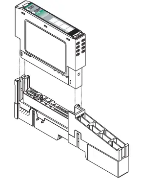
Figure 1 – POINT I/O Module with 1734-TB or 1734-TBS Terminal Base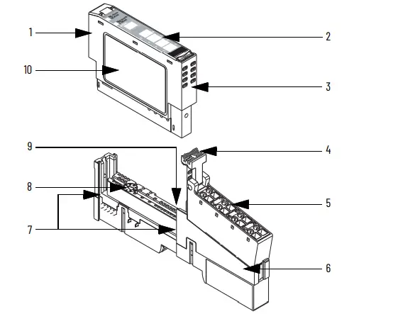
| Description | Description | ||
| 1 | Module locking mechanism | 6 | Mounting base |
| 2 | Slide-in writable label | 7 | Interlocking side pieces |
| 3 | Insertable I/O module | 8 | Mechanical keying (orange) |
| 4 | Removable Terminal Block (RTB) handle | 9 | DIN rail locking screw (orange) |
| 5 | RTB | 10 | Module wiring diagram |
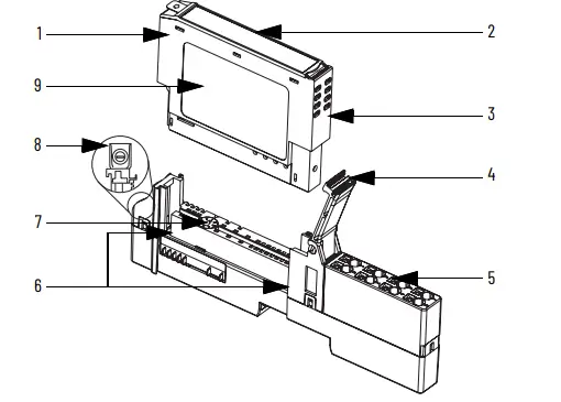
Figure 2 – POINT I/O Module with 1734-TOP or 1734-TOPS Terminal Base
| Description | Description | ||
| 1 | Module locking mechanism | 6 | Interlocking side pieces |
| 2 | Slide-in writable label | 7 | Mechanical keying (orange) |
| 3 | Insertable I/O module | 8 | DIN rail locking screw (orange) |
| 4 | RTB handle | 9 | Module wiring diagram |
| 5 | 1734-TOP or 1734-TOPS — One-piece terminal base with screw or spring clamp | ||
Install the Mounting Base
To install the mounting base on the DIN rail (Allen-Bradley® part number 199-DR1; 46277-3; EN 50022), proceed as follows:
ATTENTION: This product is grounded through the DIN rail to chassis ground. Use zinc-plated chromate-passivated steel DIN rail to assure proper grounding. The use of other DIN rail materials (for example, aluminum or plastic) that can corrode, oxidize, or are poor conductors, can result in improper or intermittent grounding. Secure DIN rail to mounting surface approximately every 200 mm (7.8 in.) and use end-anchors appropriately. Be sure to ground the DIN rail properly. See Industrial Automation Wiring and Grounding Guidelines, publication 1770-4.1, for more information.
WARNING: When used in a Class I Division 2, hazardous location, this equipment must be mounted in a suitable enclosure with proper wiring method that complies with the governing electrical codes.
- Position the mounting base vertically above the installed units (adapter, power supply, or existing module).
- Slide the mounting base down allowing the interlocking side pieces to engage the adjacent module or adapter.
- Press firmly to seat the mounting base on the DIN rail. The mounting base snaps into place.
Be sure that the orange DIN rail locking screw is in the horizontal position and that it has engaged the DIN rail.
ATTENTION: Use the end cap from your adapter or interface module to cover the exposed interconnections on the last mounting base on the DIN rail. Failure to do so could result in equipment damage or injury from electric shock.
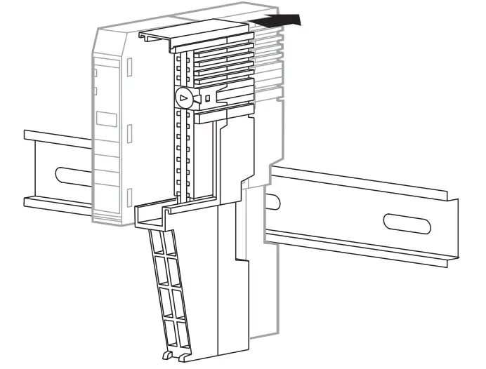
Install the Module
The module can be installed before or after base installation. Make sure that the mounting base is correctly keyed before installing the module into the mounting base. In addition, make sure that the mounting base locking screw is positioned horizontally referenced to the base.
WARNING: When you insert or remove the module while backplane power is on, an electric arc can occur. This could cause an explosion in hazardous location installations. Be sure that power is removed or the area is nonhazardous before proceeding. Repeated electrical arcing causes excessive wear to contacts on both the module and its mating connector. Worn contacts may create electrical resistance that can affect module operation.
POINT I/O Terminal Bases
To install the module, proceed as follows.
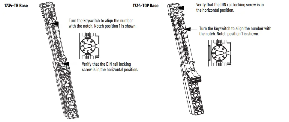
- Use a bladed screwdriver to rotate the key switch on the mounting base clockwise until the number required for the type of module being installed aligns with the notch in the base.
- Verify that the DIN rail locking screw is in the horizontal position. You cannot insert the module if the locking mechanism is unlocked.
- Insert the module straight down into the mounting base and press to secure. The module locks into place.
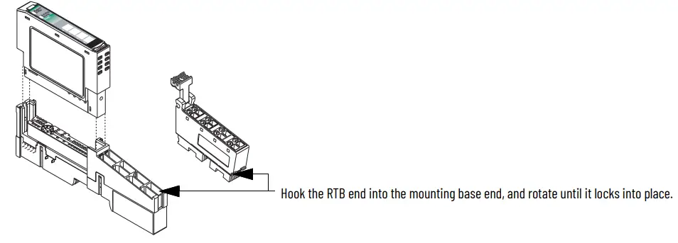
Install the Removable Terminal Block
An RTB is supplied with your wiring base assembly. To remove, pull up on the RTB handle. This allows the mounting base to be removed and replaced as necessary without removing any of the wiring. To reinsert the RTB, proceed as follows.
WARNING: When you connect or disconnect the removable terminal block (RTB) with field-side power applied, an electric arc can occur. This can cause an explosion in hazardous location installations.
Be sure that power is removed or the area is non hazardous before proceeding.
- Insert the end opposite the handle into the base unit. This end has a curved section that engages with the wiring base.
- Rotate the terminal block into the wiring base until it locks itself in place.
- If an I/O module is installed, snap the RTB handle into place on the module.
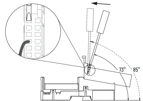
WARNING: For 1734-RTBS and 1734-RTB3S, to latch and unlatch the wire, insert a bladed screwdriver (catalog number 1492-N90 – 3 mm [0.12 in.] diameter blade) into the opening at approximately 73° (blade surface is parallel with top surface of the opening) and push up gently.
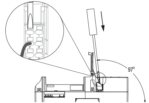
WARNING: For 1734-TOPS and 1734-TOP3S, to latch and unlatch the wire, insert a bladed screwdriver (catalog number 1492-N90 – 3 mm [0.12 in.] diameter blade) into the opening at approximately 97° (blade surface is parallel with top surface of the opening) and press in (do not push up or down).
Remove a Mounting Base
To remove a mounting base, you must remove any installed module and the module that is installed in the base to the right. Remove the RTB, if wired.
WARNING: When you insert or remove the module while backplane power is on, an electric arc can occur. This could cause an explosion in hazardous location installations.
Be sure that power is removed or the area is non hazardous before proceeding. Repeated electrical arcing causes excessive wear to contacts on both the module and its mating connector. Worn contacts may create electrical resistance that can affect module operation.
WARNING: When you connect or disconnect the removable terminal block (RTB) with field side power applied, an electric arc can occur. This could cause an explosion in hazardous location installations.
Be sure that power is removed or the area is non hazardous before proceeding.
- Unlatch the RTB handle on the I/O module.
- Pull on the RTB handle to remove the RTB.
- Press the module lock on the top of the module.
- Pull on the I/O module to remove from the base.
- Repeat steps 1, 2, 3, and 4 for the module to the right.
- Use a small-bladed screwdriver to rotate the orange base locking screw to a vertical position. This releases the locking mechanism.
- Lift straight up to remove.
Wire the Module
To wire the module, see Figure 3…Figure 8. Figure 3 – Wire the Module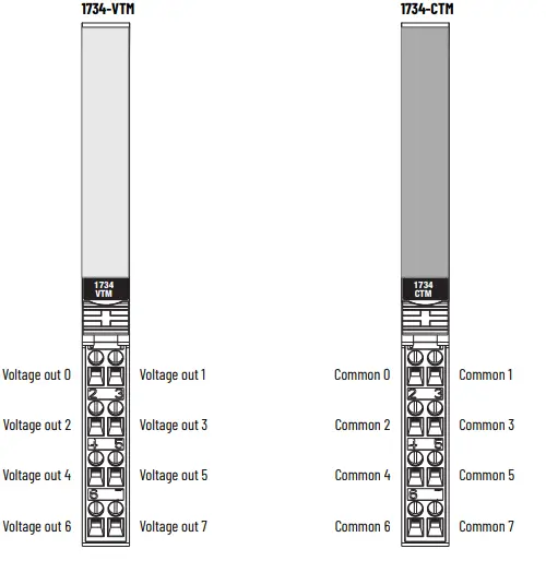
Figure 4 – Sink Input Wiring 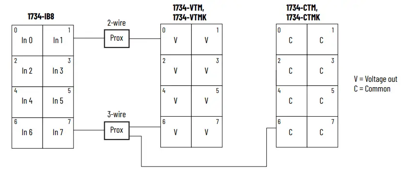 Figure 5 – Source Input Wiring
Figure 6 – Source Output Wiring

Figure 7 – Sink Output Wiring 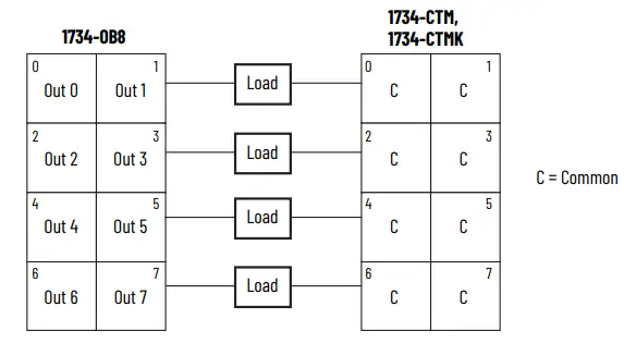
Figure 8 – General-purpose Wiring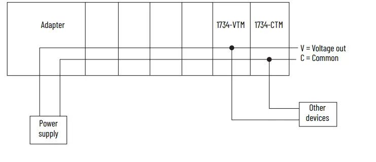
Specifications
General Specifications
| Attribute | Value |
| Indicators | None |
| Keyswitch position | 5 |
| Module location | 1734-TB, 1734-TBS, 1734-TOP, 1734-TOPS wiring base assembly |
| POINTBus™ current, max | None |
| Power dissipation, max | None |
| Thermal dissipation, max | None |
| Isolation voltage | 250V (continuous), Basic Insulation TypeType tested at 1600 V DC for 60 s, field-side to system |
| Field power bus power supply voltage range | 10. 28.8V DC, 120/240V AC |
| Field power bus output current, max | 2 A per point, 4 A module |
| Terminal base screw torque | 0.8 N•m (7 lb•in) |
| Dimensions (HxWxD), approx. | 77.5 x 12.1 x 56.6 mm (3.05 x 0.48 x 2.23 in.) |
| Weight, approx. | 30.9 g (1.09 oz) |
| Wire size | 0.25…2.5 mm2 (22…14 AWG) solid or stranded copper wire rated at 75 °C (167 °F) or greater 1.2 mm (3/64 in.) insulation maximum |
| Enclosure type rating | None (open-style) |
Environmental Specifications
| Attribute | Value |
| Temperature, operating | IEC 60068-2-1 (Test Ad, Operating Cold),IEC 60068-2-2 (Test Bd, Operating Dry Heat),IEC 60068-2-14 (Test Nb, Operating Thermal Shock):-20 °C…+55 °C (-4 °F…+131 °F) |
| Temperature, nonoperating | IEC 60068-2-1 (Test Ab, Unpackaged Nonoperating Cold),IEC 60068-2-2 (Test Bb, Unpackaged Nonoperating Dry Heat),IEC 60068-2-14 (Test Na, Unpackaged Nonoperating Thermal Shock):-40…+85 °C (-40…+185 °F) |
| Relative humidity | IEC 60068-2-30 (Test Db, Unpackaged Damp Heat): 5…95% non condensing |
| Vibration | IEC 60068-2-6 (Test Fc, Operating): 5 g @ 10…500 Hz |
| Shock, operating | EC 60068-2-27 (Test Ea, Unpackaged Shock): 30 g |
| Shock, non operating | EC 60068-2-27 (Test Ea, Unpackaged Shock): 50 g |
Certifications
| Certification (when product is marked)(1) | Value |
| c-UL-us | UL Listed Industrial Control Equipment, certified for US and Canada. See UL File E65584.UL Listed for Class I Division 2 Group A,B,C,D Hazardous Locations, certified for U.S. and Canada. See UL File E194810. |
| UK and CE | For 1734-VTM, 1734-VTMK only: UK Statutory Instrument 2016 No. 1101 and European Union 2014/35/EU EMC Directive, compliant with: EN 61131-2; Programmable Controllers (Clause 11: LVD)For 1734-CTM, 1734-CTMK, 1734-VTM, 1734-VTMK:UK Statutory Instrument 2012 No. 3032 and European Union 2011/65/EU RoHS, compliant with: EN IEC 63000; Technical documentation |
| Morocco | For 1734-VTM, 1734-VTMK only: Arrêté ministériel n° 6404-15 du 1 er muharram 1437 |
- See the Product Certification link at rok.auto/certifications for Declaration of Conformity, Certificates, and other certification details.
Additional Resources
For more information on the products that are described in this publication, use these resources. You can view or download publications at rok.auto/literature.
| Resource | Description |
| POINT I/O Modules Selection Guide, publication 1734-SG001 | Provides POINT I/O adapters and module specifications. |
| Industrial Automation Wiring and Grounding Guidelines, publication 1770-4.1 | Provides general guidelines for installing a Rockwell Automation industrial system. |
| Product Certifications website, rok.auto/certifications | Provides declarations of conformity, certificates, and other certification details. |
Rockwell Automation Support
Use these resources to access support information.
| Technical Support Center | Find help with how-to videos, FAQs, chat, user forums, Knowledgebase, and product notification updates. | rok.auto/support |
| Local Technical Support Phone Numbers | Locate the telephone number for your country. | rok.auto/phonesupport |
| Technical Documentation Center | Quickly access and download technical specifications, installation instructions, and user manuals. | rok.auto/techdocs |
| Literature Library | Find installation instructions, manuals, brochures, and technical data publications. | rok.auto/literature |
| Product Compatibility and Download Center (PCDC) | Download firmware, associated files (such as AOP, EDS, and DTM), and access product release notes. | rok.auto/pcdc |
Documentation Feedback
Your comments help us serve your documentation needs better. If you have any suggestions on how to improve our content, complete the form at rok.auto/docfeedback.
Waste Electrical and Electronic Equipment (WEEE)
 At the end of life, this equipment should be collected separately from any unsorted municipal waste.
Rockwell Automation maintains current product environmental compliance information on its website at rok.auto/pec.
Rockwell Otomasyon Ticaret A.Ş. Kar Plaza İş Merkezi E Blok Kat:6 34752 İçerenköy, İstanbul, Tel: +90 (216) 5698400 EEE Yönetmeliğine Uygundur
Connect with us.
rockwellautomation.com
expanding human possibility•
AMERICAS; Rockwell Automation, 1201 south second street, Milwaukee, WI 53204-2496 USA, Tel; (1) 414.382.2000 EUROPE/ MIDDLE EAST/AFRICA: Rockwell Automation NV, Pegasus Park, De Kleetlaan 12B, 1831 Diegem, Belgium, Tel: (32)2GB3 0600
ASIA PACIFIC: Rockwell Autornation SEA Pte Ltd. 2 Corporation Road. #04-CS. Main Lobby. Corporation Place, Singapore 618494. Tel: (ES)6SID 660B
UNITED KINGOOM: Rockwell Automation Ltd., Pittield. Kiln Farm, Milton Keynes, MKII 3DR, United Kingdom, Tel;(44)(190)838-800
Allen-Bradley, expanding human possibility, POINT I/O, POINTBus, Rockwell Automation, and TechConnect are trademarks of Rockwell Automation, Inc. Trademarks not belonging to Rockwell Automation are property of their respective companies.
Publication 1734-IN024B-EN-E – December 2024 | Supersedes Publication 1734-IN024A-EN-E – March 2005 Copyright © 2024 Rockwell Automation, Inc. All rights reserved.
FAQ
Q: Are the conformal coated catalog numbers different from non-conformal coated ones?
A: No, catalog numbers with the suffix ‘K’ that are conformal coated have the same specifications as non-conformal coated catalogs.
Documents / Resources
 |
Allen-Bradley 1734-CTM Common Terminal Module and Voltage Terminal Module [pdf] Instruction Manual 1734-CTM, 1734-CTMK, 1734-VTM, 1734-VTMK, 1734-CTM Common Terminal Module and Voltage Terminal Module, 1734-CTM, Common Terminal Module and Voltage Terminal Module, Voltage Terminal Module |


