![]() EL00IG Ground Wireless Loop Detection System
EL00IG Ground Wireless Loop Detection System
Instructions
Specifications
Model E-LOOP: EL00IG & EL00IG-RAD
Frequency: 433.39 MHz.
Security: 128-bit AES encryption.
Range: up to 50 yards.
Battery life: up to 6-10 years.
Battery type: 14500 mA battery.
Transmitting power: <10mW.
COMMERCIAL INGROUND
VERSION 3.0
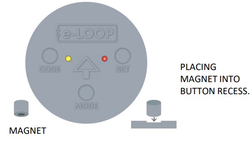
Changing mode using a magnet (EL0OIG-RAD only)
Note: e-loop comes preset in presence mode.
- Place a magnet on the MODE recess until the yellow starts LED flashing indicating presence mode, to change to exit mode place the magnet on the SET recess, the red LED will start flashing, to change to parking mode place the magnet on the MODE recess, the Yellow LED will come on solid.
- Wait 5 seconds until all LED’s flash, we have now entered the confirmation menu, move to Step 3 or wait a further 5 seconds until all LED’s flash 3 times to exit menu.
- Confirmation mode.
Once in the confirmation menu the red LED will be on solid meaning confirmation is not enabled, to enable place magnet on code recess, the yellow LED and red LED will be on, confirmation is now enabled, wait 5 seconds and both LED’s will flash 3 times indicating menu has now been exited.
 Safety instructions: Before proceeding with the product’s installation, check that all the materials are in good working order and suited to the intended applications.
Warning! – Exhausted batteries contain polluting substances; therefore they may not be disposed of together with unsorted household waste. They must be disposed of separately according to the regulations locally in force.
Installation Warnings

The e-LOOP should be installed in a location that is always visible. Do not place the eLOOP in a dip or area where snow or water can sit.
Keep e-LOOP central in the driveway so as it passes directly underneath the vehicles.
DISCLAIMER: UNITS WITH THE PRESENCE FEATURE IS NOT TO BE USED AS A SOLE SAFETY DEVICE & SHOULD BE USED IN CONJUNCTION WITH STANDARD GATE SAFETY PRACTICES.
Disposal: The packaging must be disposed of in the local recyclable containers. According to the European Directive 2002/96/EC on waste electrical equipment, this device must be properly disposed of, after usage in order to ensure a recycling of the materials used.
Old accumulators and batteries may not be disposed of in the household waste, since they contain pollutants and must be properly disposed of in municipal collection points or in the containers of the dealer provided. Country-specific regulations must be observed.
STEP 2: Fitting e-LOOP
(Refer to diagram below)
- Drill (89-92mm) hole 65-70mm deep. Ensure the hole is clean and dry before fitting.
- Measure down before inserting the e-LOOP to ensure it will fit flush with the driveway surface, then pour sikaflex or similar compound into the base of hole.
- Insert the e-LOOP by pushing down until flush with driveway surface.
NOTE: Ensure e-LOOP is fitted in a well drained area, as water over the e-LOOP can effect the radar detection system.
STEP 3: Calibrate e-LOOP
- Move any metal objects away from the e-LOOP.
- Place magnet into the SET button recess on the e-LOOP until the red LED flashes twice, then remove the magnet.
- The e-LOOP will take about 5 seconds to calibrate and once complete, the red LED will flash 3 times.
The system is now ready.
NOTE: After calibration, you may get an error indication.
ERROR 1: Low radio range – yellow LED flashes 3 times before red LED flashes 3 times.
ERROR 2: No radio connection – yellow and red LED flashes 3 times before red LED flashes 3 times.
Uncalibrate the e-LOOP
Place the magnet into the SET button recess until red LED flashes 4 times, e-LOOP is now uncalibrated.
Changing mode using a magnet (EL0OIG-RAD only)
Note: e-loop comes preset in presence mode.
- Place a magnet on the MODE recess until the yellow starts LED flashing indicating presence mode, to change to exit mode place the magnet on the SET recess, the red LED will start flashing, to change to parking mode place the magnet on the MODE recess, the Yellow LED will come on solid.
- Wait 5 seconds until all LED’s flash, we have now entered the confirmation menu, move to Step 3 or wait a further 5 seconds until all LED’s flash 3 times to exit menu.
- Confirmation mode.
Once in the confirmation menu the red LED will be on solid meaning confirmation is not enabled, to enable place magnet on code recess, the yellow LED and red LED will be on, confirmation is now enabled, wait 5 seconds and both LED’s will flash 3 times indicating menu has now been exited.
Parameters that can be altered on EL00IG-RAD (Requires e-Diagnostic Remote or E-Trans-200):
- Mode is set to PRESENCE but can be changed to EXIT mode. NOTE: do not use presence mode as a personal safety device.
- Activation detection level
- X, Y, Z axis sensitivity
- Radar read time
- Release trip point
- Start lens detection range
- Measure lens detection range
- Radar trip sensitivity
- Radar confirm ON/OFF
Document updated: 05/27/24.
![]() E. sales@aesglobalus.com
E. sales@aesglobalus.com
www.aesglobalus.com
T: +1 – 321 – 900 – 4599
Documents / Resources
 |
AES EL00IG Ground Wireless Loop Detection System [pdf] Instructions EL00IG, EL00IG-RAD, EL00IG Ground Wireless Loop Detection System, EL00IG, Ground Wireless Loop Detection System, Wireless Loop Detection System, Loop Detection System, Detection System, System |