1. Introduction
The SUMRY HGX 4.5KW Pure Sine Wave Hybrid Inverter is an advanced off-grid solar inverter designed to provide reliable, clean, and quiet AC energy for various applications. It features a built-in 150A MPPT solar charger and supports a high PV input range of 55V-450Vdc. This inverter can operate without batteries on sunny days and offers flexible power management through its SBU (Solar-Battery-Utility) mode. Its smart battery charger design optimizes battery performance, and the unit includes a 6.5-inch display with touchable buttons for easy configuration and monitoring.

Figure 1: SUMRY 4500W Pure Sine Wave Hybrid Inverter
2. Safety Information
Please read all instructions and warnings carefully before installation and operation. Failure to follow these instructions may result in electric shock, fire, or serious injury.
- All wiring must be performed by qualified personnel.
- Ensure the inverter is turned off and disconnected from all power sources (PV, battery, utility) before performing any wiring or maintenance.
- Do not disassemble the inverter. There are no user-serviceable parts inside.
- Install the inverter in a well-ventilated area, away from flammable materials and corrosive gases.
- Ensure proper grounding of the inverter.
- Use appropriate circuit breakers for PV, battery, and AC connections as specified.
- Avoid touching live terminals.
- Keep children away from the inverter.
3. Product Overview
The inverter features a user-friendly design with a clear display and accessible connection points. Below is a diagram illustrating the main components and their functions.

Figure 2: Product Overview and Connection Points
- LCD display
- Status indicator
- Charging indicator
- Fault indicator
- Function touch buttons (ESC, UP, DOWN, ENTER)
- Power on/off switch
- AC input
- AC output
- PV input
- Battery input
- Circuit breaker
- RS485/RS232 communication port

Figure 3: Inverter Top and Side Views
4. Specifications
Detailed technical specifications for the SUMRY HGX 4.5KW inverter:
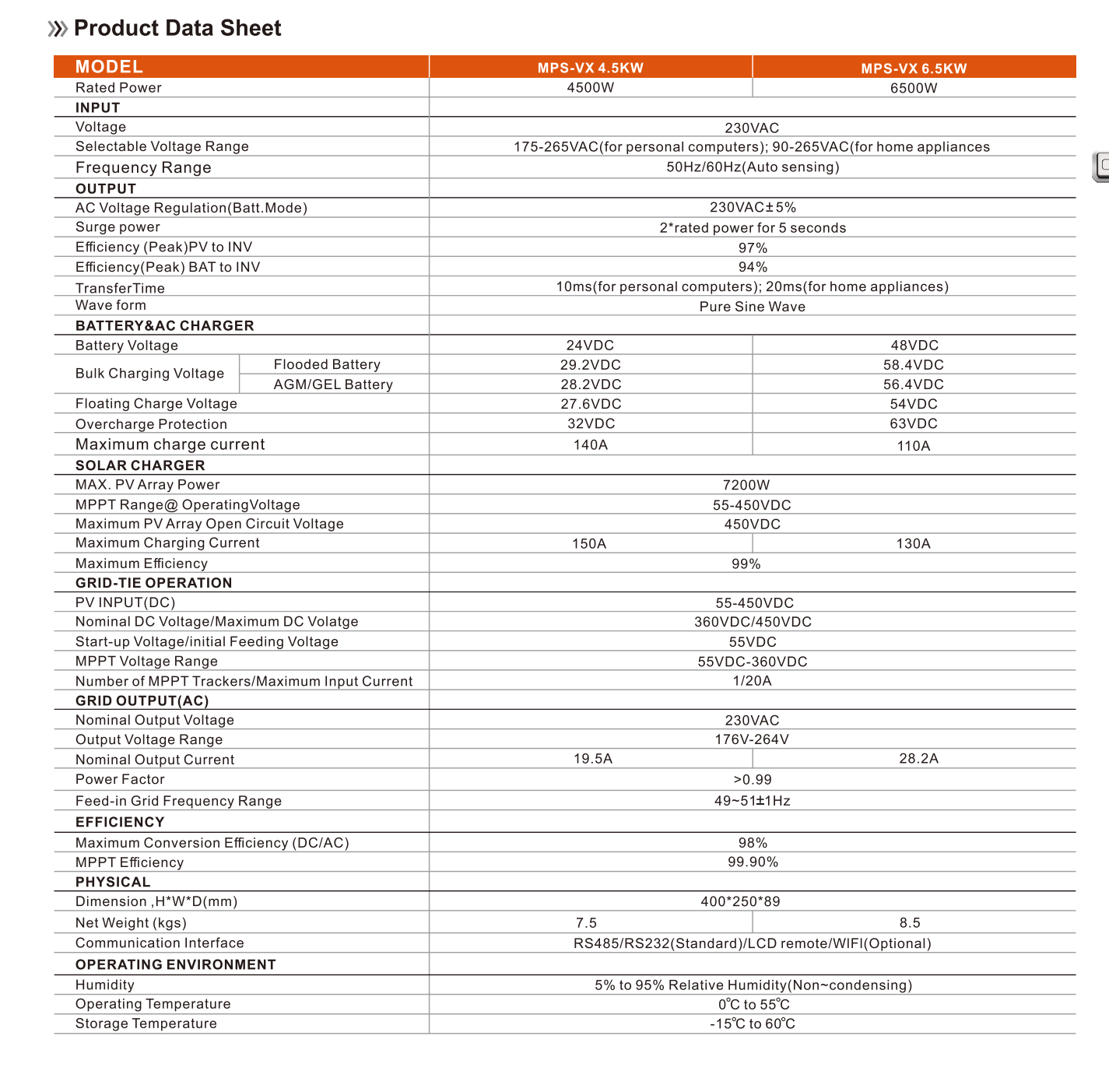
Figure 4: Product Data Sheet
| Category | Parameter | Value (MPS-VX 4.5KW) |
|---|---|---|
| Model | Rated Power | 4500W |
| INPUT | Voltage | 230VAC |
| Selectable Voltage Range | 175-265VAC (for personal computers); 90-265VAC (for home appliances) | |
| Frequency Range | 50Hz/60Hz (Auto sensing) | |
| Input Voltage | 230v | |
| OUTPUT | AC Voltage Regulation (Batt.Mode) | 230VAC±5% |
| Surge power | 2*rated power for 5 seconds | |
| Efficiency (Peak)PV to INV | 97% | |
| Efficiency (Peak)BAT to INV | 94% | |
| Transfer Time | 10ms (for personal computers); 20ms (for home appliances) | |
| Wave form | Pure Sine Wave | |
| BATTERY & AC CHARGER | Battery Voltage | 24VDC |
| Bulk Charging Voltage (Flooded Battery) | 29.2VDC | |
| Bulk Charging Voltage (AGM/GEL Battery) | 28.2VDC | |
| Floating Charge Voltage | 27.6VDC | |
| Overcharge Protection | 32VDC | |
| Maximum Charging Current | 140A | |
| SOLAR CHARGER | MAX. PV Array Power | 7200W |
| MPPT Range@OperatingVoltage | 55-450VDC | |
| Maximum PV Array Open Circuit Voltage | 450VDC | |
| Maximum Charging Current | 150A | |
| MPPT Efficiency | 99% | |
| GRID-TIE OPERATION | PV INPUT (DC) | 55-450VDC |
| Nominal DC Voltage/Maximum DC Voltage | 360VDC/450VDC | |
| Start-up Voltage/Initial Feeding Voltage | 55VDC | |
| MPPT Voltage Range | 55VDC-360VDC | |
| Number of MPPT Trackers/Maximum Input Current | 1/20A | |
| GRID OUTPUT (AC) | Nominal Output Voltage | 230VAC |
| Output Voltage Range | 176V-264V | |
| Nominal Output Current | 19.5A | |
| Power Factor | >0.99 | |
| Feed-in Grid Frequency Range | 49-51±1Hz | |
| EFFICIENCY | Maximum Conversion Efficiency (DC/AC) | 98% |
| MPPT Efficiency | 99.90% | |
| PHYSICAL | Dimension, H*W*D(mm) | 400*250*89 |
| Net Weight (Kg) | 7.5 | |
| Size | 39*26*9cm | |
| OPERATING ENVIRONMENT | Communication Interface | RS485/RS232 (Standard)/LCD remote/WIFI (Optional) |
| Humidity | 5% to 95% Relative Humidity (Non-condensing) | |
| Operating Temperature | 0°C to 55°C | |
| Storage Temperature | -15°C to 60°C |
5. Installation and Setup
Proper installation is crucial for the safe and efficient operation of your inverter. Please follow these steps carefully.
5.1 System Diagram
The inverter integrates solar, battery, and utility power sources to supply your home appliances.

Figure 5: Typical System Connection Diagram
5.2 Wiring Connections
Refer to the following video for a visual guide on wiring the inverter. Ensure all connections are secure and follow local electrical codes.
Video 1: Inverter Wiring Demonstration
PV Connection
CAUTION: Before connecting to PV modules, please install separately a DC circuit breaker between the inverter and PV modules. All wiring must be performed by a qualified personnel. It's very important for system safety and efficient operation to use appropriate cable for PV module connection. To reduce risk of injury, please use the proper recommended cable size as below.

Figure 6: Solar Photovoltaic Panel Wiring Method (Series/Parallel)
- In Series: Increase the voltage of the system. This voltage needs to be less than the hybrid inverter's maximum input voltage Voc/inverter. The entire photovoltaic system should use the same type of photovoltaic panel.
- In Parallel: Increases the current of the system. This current should not exceed the maximum PV input current of the hybrid inverter.
PV cable dimensions: 6-8A/mm²

Figure 7: PV Connection Wire Size and Torque Values
When selecting proper PV modules, be sure to consider below parameters:
- Open circuit Voltage (Voc) of PV modules not exceeds max. PV array open circuit voltage of inverter.
- Open circuit Voltage (Voc) of PV modules should be higher than min. PV Array MPPT Voltage range.
Battery Connection
The inverter is compatible with various 24V battery types, including Flooded (FLD), Gel, Lithium-ion (LI), AGM/Sealed (SLD), and user-customizable battery settings.

Figure 8: Compatible Battery Types
Connect the battery cables to the designated battery input terminals (+ and -) on the inverter. Ensure correct polarity. The inverter also features built-in lithium battery automatic activation.
AC Input/Output and Grounding
Connect the AC input from the utility grid and the AC output to your home appliances using appropriate wiring. Ensure the ground wire is securely connected to the inverter's grounding terminal.
6. Operating Instructions
The inverter features a 6.5-inch LCD display and touchable buttons for easy operation and monitoring.
6.1 Display and Button Functions
Use the ESC, UP, DOWN, and ENTER buttons to navigate through the display menus and configure settings. The display shows real-time information such as input/output voltage, battery status, and load.
6.2 Operating Modes
The inverter supports various operating modes to optimize power usage:

Figure 9: Inverter Operating Modes
- Only Solar: Prioritizes solar power.
- Utility Priority: Prioritizes utility grid power.
- Solar & Utility: Utilizes both solar and utility power.
- SBU Mode: Utility Power, battery, and PV Power complement each other. This mode allows the inverter to work without batteries on sunny days.
You can configure the AC/Battery input priority via the LCD settings.
6.3 Remote Monitoring (Optional)
The inverter supports WiFi monitoring functionality (optional) via a dedicated app. Connect the WiFi dongle to the communication port to enable remote monitoring and control.

Figure 10: Remote Monitoring via App
7. Maintenance
Regular maintenance ensures the longevity and optimal performance of your inverter.
- Cleaning: Periodically clean the inverter's exterior and ventilation openings to prevent dust accumulation, which can affect cooling. An anti-dust kit is available for harsh environments (optional).
- Connection Checks: Regularly inspect all wiring connections (PV, battery, AC, ground) to ensure they are tight and free from corrosion.
- Battery Health: Monitor battery voltage and performance. Ensure batteries are maintained according to their manufacturer's guidelines.
- Firmware Updates: Check the manufacturer's website for any available firmware updates to ensure your inverter has the latest features and bug fixes.
8. Troubleshooting
If you encounter issues with your inverter, refer to the following basic troubleshooting steps:
- No Power/Display Off: Check all power connections (battery, PV, utility). Ensure the power switch is in the 'ON' position. Verify battery voltage is within the operating range.
- No AC Output: Check AC output connections and ensure the load is not exceeding the inverter's rated power. Check for any fault indicators on the display.
- Fault Indicator On: Refer to the inverter's display for specific error codes or messages. Common faults include over-load, over-temperature, and output short circuit. The inverter has built-in protection systems for these conditions.
- PV Not Charging: Verify PV panel connections and ensure sufficient sunlight. Check PV input voltage and current on the display.
- Cold Restart Function: The inverter supports a cold restart function, which can be used to reset the system in certain fault conditions.
- Restore Default Settings: The inverter allows restoring default settings with one click if configuration issues arise.

Figure 11: Intelligent Protection Systems
9. User Tips
- For optimal battery life, ensure your battery type is correctly configured in the inverter settings.
- Regularly monitor your system's performance via the LCD display or the optional WiFi monitoring app to identify and address any potential issues early.
- When operating without batteries, ensure your PV array is adequately sized to meet the load demands, especially during peak usage.
10. Warranty and Support
For warranty information, technical support, or service inquiries, please contact your retailer or the manufacturer directly. Keep your purchase receipt and product serial number handy for faster service.


