1. Introduction
This manual provides essential information for the safe and efficient operation of your SUMRY 4500W Hybrid Solar Inverter. Please read this manual thoroughly before installation and use, and keep it for future reference.
Key Features:
- Off-Grid Solar Inverter
- Ability to work without batteries on sunny days
- Adjustable AC voltage (110VAC or 220VAC) in Battery Mode
- SBU Mode: Utility Power, battery, and PV Power complement each other
- Pure sine wave output
- Unique glass top cover design with 6.5-inch display and touchable buttons
- Built-in 150A MPPT solar charger (Max PV 7200W)
- High PV input range: 55V-450Vdc
- Smart battery charger design for optimized battery performance
- Configurable AC/Battery input priority via LCD setting
- Auto restart while PV is recovering
- Over-load, over temperature, and output short circuit protection
- Cold restart function
- Built-in lithium battery automatic activation
- Communication with RS232/RS485
- Optional WiFi monitoring function
- Optional Anti-dust kit for harsh environments
- Restore default settings with one click
2. Safety Information
Always observe the following safety precautions to reduce the risk of injury and to ensure the safe operation of the inverter:
- All wiring must be performed by qualified personnel.
- Ensure proper cable sizing for PV connections to prevent risk of injury and ensure system safety.
- Do not attempt to disassemble or repair the inverter yourself. Refer to qualified service personnel.
- Keep the inverter away from flammable materials and moisture.
- Ensure adequate ventilation around the inverter to prevent overheating.
- Before connecting to PV modules, install a DC circuit breaker between the inverter and PV modules.
3. Product Overview
The SUMRY Hybrid Solar Inverter integrates a solar charge controller, inverter, and battery charger into one unit to offer uninterruptible power support. It features a 6.5-inch LCD display and touchable buttons for easy configuration and monitoring.

Components: 1. LCD display, 2. Status indicator, 3. Charging indicator, 4. Fault indicator, 5. Function touch buttons, 6. Power on/off switch, 7. AC input, 8. AC output, 9. PV input, 10. Battery input, 11. Circuit breaker, 12. RS485/RS232 communication port.
Inverter Application:
The inverter is designed to power various household appliances and electronic devices.

The inverter can support devices such as LED TVs, phones & pads, refrigerators, drills, computers, induction cookers, washing machines, and printers.
4. Setup
4.1 Unpacking and Inspection
Upon receiving your inverter, carefully unpack it and inspect for any damage. Ensure all components listed in the packing list are present. If any damage or missing parts are found, contact your supplier immediately.
4.2 Physical Installation
Choose a suitable location for the inverter that is well-ventilated, dry, and away from direct sunlight or heat sources. Ensure the mounting surface can support the inverter's weight (approximately 10KG).
4.3 Wiring Instructions
Proper wiring is critical for the safe and efficient operation of your hybrid inverter. Refer to the following diagrams and instructions. All wiring should be performed by a qualified electrician.
This video demonstrates the step-by-step process of connecting the PV, AC input, AC output, and battery cables to the SUMRY Hybrid Inverter, including securing the connections and installing the communication module.
General Wiring Diagram:

Installation Knowledge: Before installing and using the inverter, it is recommended to install 4 circuit breakers in the following 4 positions: 1. Between the battery pack and the inverter battery input. 2. Between the solar panel and the photovoltaic input of the inverter. 3. Between the power input of the grid and the inverter. 4. Between inverter output and load. The circuit breaker is to effectively prevent misconnection or reverse connection of the mains input and the inverter output; when there is a short circuit, load short circuit, or overload in the output, the circuit breaker can directly cut off the circuit to protect the inverter.
PV Connection:
CAUTION: Before connecting to PV modules, please install separately a DC circuit breaker between the inverter and PV modules.
WARNING! All wiring must be performed by a qualified personnel. It's very important for system safety and efficient operation to use appropriate cable for PV module connection. To reduce risk of injury, please use the proper recommended cable size as below.
| Model | Wire Size | Cable (mm²) | Torque value (max) |
|---|---|---|---|
| 4.5KW/6.5KW | 1 x 12AWG | 4 | 1.2 Nm |
PV Module Selection:
When selecting proper PV modules, please be sure to consider below parameters:
- Open circuit Voltage (Voc) of PV modules must not exceed max. PV array open circuit voltage of inverter.
- Open circuit Voltage (Voc) of PV modules should be higher than min. PV Array MPPT Voltage range.
| INVERTER Model | 4.5KW | 6.5KW |
|---|---|---|
| Max. PV Array Open Circuit Voltage | 450Vdc | |
| PV Array MPPT Voltage Range | 120Vdc~450Vdc | |
Take 250Wp PV module as an example. After considering above two parameters, the recommended module configurations are listed as below table.

This table provides examples of solar input configurations (Min in serial, Max in serial, Q'ty of panels, Total input power) for 250Wp PV modules with specific Vmp, Imp, Voc, and Isc values.
Solar Photovoltaic Panel Wiring Method:

In Series: Increases the voltage of the system. This voltage needs to be less than the hybrid inverter PV maximum input voltage Voc/inverter. The entire photovoltaic system should use the same type of photovoltaic panel. Example: 41.92V * 6 = 251.52V, 10.35A.
In Parallel: Increases the current of the system. This current should not exceed the maximum PV input current of the hybrid inverter. Example: 10.35A * 2 = 20.7A, 41.92V * 3 = 125.76V. PV cable dimensions: 6-8A/mm².
Battery Compatibility:
The inverter is compatible with multiple battery types, offering flexibility for your energy storage needs.

Compatible battery types include Flooded, Gel, Lithium-iron phosphate, Lithium-ion, AGM/Sealed, and user-customizable battery settings.
5. Operating Instructions
5.1 Initial Power-Up
After all connections are securely made and verified, switch on the inverter using the ON/OFF button. The LCD display will illuminate, indicating the inverter is starting up.
5.2 LCD Display and Touch Buttons
The 6.5-inch LCD display provides real-time information about the inverter's status, input/output voltages, battery charge, and load. The touchable buttons (ESC, UP, DOWN, ENTER) allow for navigation through menus and configuration of settings.
5.3 Operating Modes
The inverter supports different operating modes to optimize power usage based on available sources.

SUB Mode: Solar charging as first priority. Utility will supply power to the loads when solar energy is not sufficient. Battery provides power only when solar energy and utility are not available.
SBU Mode: Solar charging as first priority. Battery will supply power to the loads when solar energy is not sufficient. Utility provides power only when battery voltage drops to warning voltage.

You can configure the AC/Battery input priority via the LCD settings to choose between 'Only Solar', 'Utility Priority', or 'Solar & Utility' modes.
5.4 Monitoring and Control (Optional WiFi)
For enhanced monitoring and control, an optional WiFi module can be connected to the inverter. This allows you to monitor the system's performance and adjust settings remotely via the 'smartess App' available on app stores.

The smartess App provides real-time data and control options for your inverter system.
6. Maintenance
Regular maintenance ensures the longevity and optimal performance of your inverter.
- Cleaning: Periodically clean the exterior of the inverter with a dry cloth. Ensure ventilation openings are free from dust and debris.
- Connection Checks: Regularly inspect all wiring connections (PV, battery, AC input/output) to ensure they are tight and free from corrosion.
- Battery Health: If using lead-acid batteries, check electrolyte levels and terminal conditions as per battery manufacturer guidelines. For lithium batteries, monitor their state of charge and health via the inverter's display or app.
- Firmware Updates: Check the manufacturer's website for any available firmware updates to ensure your inverter has the latest features and bug fixes.
7. Troubleshooting
The inverter is equipped with intelligent protection systems to prevent damage. If an issue occurs, the fault indicator (4 in Figure 3.1) may light up, and an error code might be displayed on the LCD.

The inverter includes protections against Overload, Overheating, High/Low Voltage, Battery issues, Short Circuit, Overcurrent, Anti-Reverse connection, and Power Failure.
Common Issues and Solutions:
- Overload Protection: If the load connected exceeds the inverter's capacity, it will trigger overload protection. Reduce the load and restart the inverter.
- Over Temperature Protection: Ensure adequate ventilation. Clean any dust from the vents. If the ambient temperature is too high, consider relocating the inverter or improving cooling.
- Output Short Circuit Protection: Check all output wiring for short circuits. Correct any faults before restarting.
- Cold Restart Function: The inverter supports a cold restart function, which can be useful in certain fault conditions. Refer to the LCD menu for this option.
- No Output/Low Output Voltage: Check battery voltage, PV input, and AC input connections. Ensure the correct operating mode is selected.
If the problem persists after attempting these solutions, contact technical support.
8. Specifications
Detailed technical specifications for the SUMRY HGX 4.5kw Hybrid Solar Inverter.
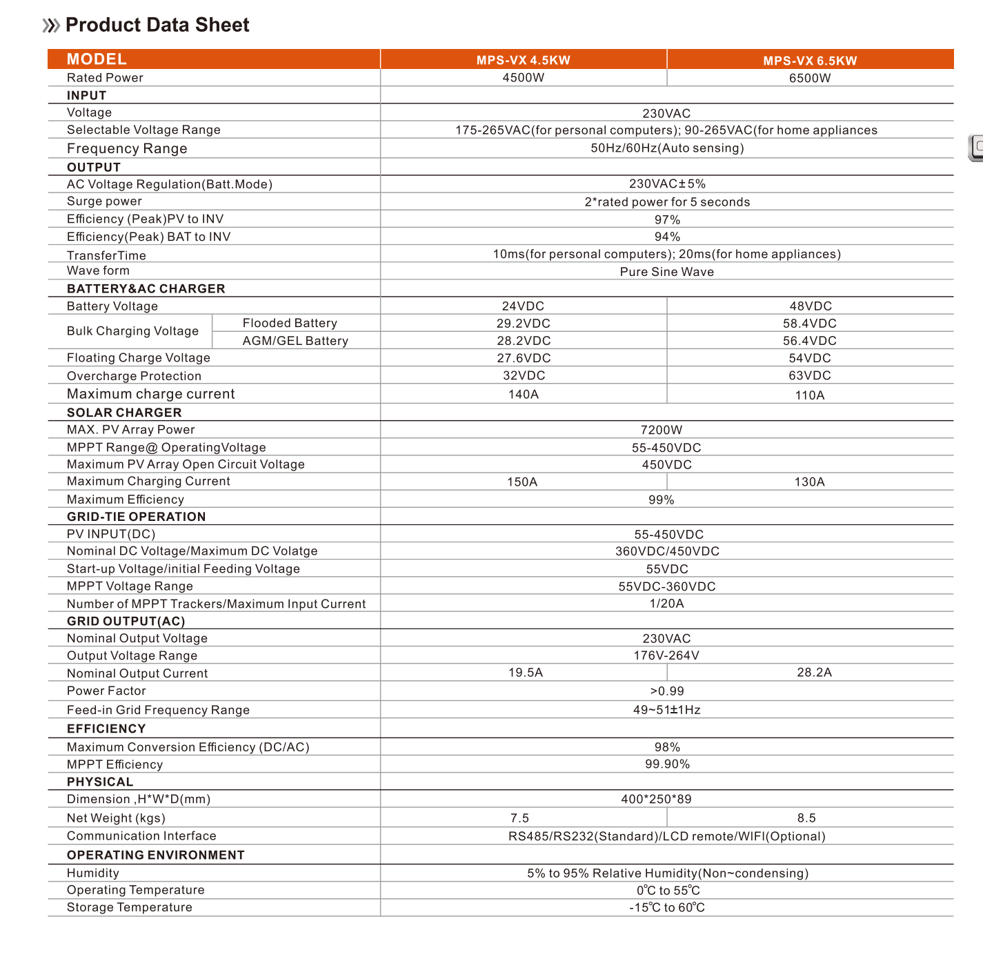
This table provides comprehensive specifications for the MPS-VX 4.5KW and MPS-VX 6.5KW models, including input, output, battery & AC charger, solar charger, grid-tie operation, efficiency, physical dimensions, and operating environment details.
| Attribute | Value |
|---|---|
| Model Number | HGX 4.5kw |
| Output Current | 33A |
| Size | 400*250*89MM |
| Output Type | SINGLE |
| Weight | 10KG |
| Brand Name | SUMRY |
| Output Frequency | 50/60Hz |
| Is Smart Device | Yes |
| Origin | Mainland China |
| Certification | CE |
| INPUT Voltage | 230v |
| Frequency Range | 50Hz/60Hz (Auto sensing) |
| Surge power | 2*rated power for 5 seconds |
| Transfer Time | 10ms (for personal computers); 20ms (for home appliances) |
| Wave form | Pure Sine Wave |
| Battery Voltage | 24VDC |
| Floating Charge Voltage | 27.6VDC |
| Overcharge Protection | 32VDC |
| Maximum charge current | 140A |
| MAX. PV Array Power | 7200W |
| MPPT Range@OperatingVoltage | 55-450VDC |
| Maximum Charging Current | 150A |
| Maximum Efficiency | 99% |
| Nominal Output Current | 19.5A |
| Communication Interface | RS485/RS232 (Standard)/LCD remote/WIFI (Optional) |
| Feature Highlights | Off Grid Solar Inverter, Working without batteries in sunny day, Pure sine wave solar inverter, 6.5inch display and touchable buttons, High PV input range from 55V-450Vdc, Smart battery charger design, Over-load, over temperature and output short circuit protection, Cold restart function |
9. User Tips
- Output Voltage Flexibility: While the inverter's primary output is 220-240V, it can be configured in Battery Mode to adjust the AC voltage to either 110VAC or 220VAC, offering versatility for different appliance requirements.
- Optimizing Solar Usage: Utilize the SBU (Solar-Battery-Utility) mode to prioritize solar power, then battery power, and only use utility power as a last resort, maximizing your energy independence.
- Remote Monitoring: Consider installing the optional WiFi module and 'smartess App' for convenient remote monitoring of your system's performance and status.
10. Warranty and Support
For warranty information, technical support, or service inquiries, please contact your original point of purchase or the SUMRY customer service department. Ensure you have your product model number and purchase details available when contacting support.