1. Introduction and Overview
The GDEQ0426T82-FT01C is a 4.26-inch reflective electrophoretic E-Ink display module featuring integrated front-light and capacitive touch screen capabilities. This ultra-thin module combines the E Ink display, capacitive touch, and front lighting into a single unit with a thickness of only 1.98mm, offering a compact and efficient solution for various smart display projects.
It is designed for DIY smart display projects, providing high contrast and ultra-low power consumption. The display supports up to 4 grayscale levels and features an SSD1677 driver IC for display control and an FT6336U controller for capacitive touch functionality.
Key Features:
- Ultra-Thin Integrated Design: Combines E Ink display, capacitive touch, and front lighting into a 1.98mm thick module.
- Exceptional Display: 4.26-inch diagonal active area with 800 x 480 pixels resolution (~219 PPI).
- High Contrast: Black and White display with up to 4 grayscale levels.
- Ultra-Low Power Consumption: Efficient operation with low power draw.
- Capacitive Touch Screen: Responsive touch control using FT6336U controller (2.8~3.6V).
- Front Light System: Adjustable cool/warm LEDs for comfortable reading in low-light conditions.
- Wide Operating Temperature: 0℃ to 50℃.
- Interface: SPI for display and I2C for touch.
2. Specifications
2.1 General Specifications
| Parameter | Specification | Unit |
|---|---|---|
| Part Number | GDEQ0426T82-FT01C | - |
| Type | Dot Matrix | - |
| Screen Size | 4.26 | inch |
| Resolution | 800(H) x 480(V) | pixels |
| Pixel Pitch | 0.116 x 0.116 | mm |
| Color | Black and White | - |
| Max Grayscale | 4 | - |
| Outline Dimension | 105.33(H) x 62.37(V) x 1.98(D) | mm |
| Active Area | 92.8 x 55.68 | mm |
| Driver IC | SSD1677 | - |
| Interface | SPI | - |
| Connector | 24-pin FPC, pitch: 0.5 mm | - |
| Module Weight | 20.5 ± 10% | gram |
| Operating Temperature | 0℃ ~ 50℃ | - |
| Storage Temperature | -25℃ ~ 70℃ | - |
2.2 Performance Specifications
| Parameter | Specification | Unit |
|---|---|---|
| Full Refresh Time | 3.5 | seconds |
| Fast Refresh Time | 1.5 | seconds |
| Partial Refresh Time | 0.42 | seconds |
| Power Consumption (Refresh) | 26.4 | mW |
| Standby Power Consumption | 0.0066 | mW |
| White Reflectivity | 30-35 | % |
| Contrast Ratio | 8:1 | - |
| Life Time | 1,000,000 times or 5 years | - |
2.3 Touchscreen Specifications
| Parameter | Specification | Unit |
|---|---|---|
| Touch IC | FT6336U | - |
| Touch Connector | 6 Pin FPC | - |
| Touch Voltage | 2.8 - 3.6 | V |
| Operating Current | 4.32 | mA |
| Standby Current | 55 | µA |
2.4 Front-Lit Specifications
| Parameter | Specification | Unit |
|---|---|---|
| Front-Lit Connector | 6 pin FPC | - |
| Number of LEDs | 7 | - |
| Circuit Mode | Series connection | - |
| Operating Voltage | ≤15 | V |
| Operating Current | ≤15 | mA |
2.5 Absolute Maximum Ratings
Exceeding these ratings may cause permanent damage to the device. Functional operation should be restricted to the limits specified in the DC Characteristics tables.
| Item | Symbol | Min | Max | Unit |
|---|---|---|---|---|
| Logic supply voltage | VCI | -0.5 | +4.0 | V |
| Logic Input voltage | VIN | -0.5 | VDDIO+0.5 | V |
| Logic Output voltage | VOUT | -0.5 | VDDIO+0.5 | V |
| Operating Temp. | Top | 0 | +50 | °C |
| Storage Temp | Tstg | -25 | +70 | °C |
3. Setup and Connection
3.1 Module Interface Pin Assignment
The display module connects via a 24-pin FPC connector. Below is the pin assignment for proper integration:
| Pin No. | Pin Name | Description |
|---|---|---|
| 1, 4 | NC | No Connection |
| 2 | GDR | N-Channel MOSFET gate drive control pin. |
| 3 | RESE | Current Sense Input for the control loop |
| 5 | VSH2 | Positive Source driving voltage. Connect a stabilizing capacitor between VSH2 and VSS. |
| 6, 7 | NC | No Connection |
| 8 | BS1 | SPI interface selection (3-wire H active or 4-wire L active). |
| 9 | BUSY | Busy state output pin (High when chip is operating). |
| 10 | RES# | Reset signal input (Active Low). |
| 11 | D/C# | Data/Command control pin connecting to the MCU. |
| 12 | CS# | Chip select input connecting to the MCU. |
| 13 | SCL | Serial clock pin for interface. |
| 14 | SDA | Serial data pin for interface. |
| 15 | VDDIO | Power for interface logic pins. |
| 16 | VCI | Power input pin for the chip. |
| 17 | VSS | Ground |
| 18 | VDD | Core logic power pin. Regulated internally from VCI. |
| 19 | VPP | Power Supply for OTP Programming. |
| 20 | VSH1 | Positive Source driving voltage. Connect a stabilizing capacitor between VSH1 and VSS. |
| 21 | VGH | Positive Gate driving voltage. Connect a stabilizing capacitor between VGH and VSS. |
| 22 | VSL | Negative Source driving voltage. Connect a stabilizing capacitor between VSL and VSS. |
| 23 | VGL | Negative Gate driving voltage. Connect a stabilizing capacitor between VGL and VSS. |
| 24 | VCOM | VCOM driving voltage. Connect a stabilizing capacitor between VCOM and VSS. |
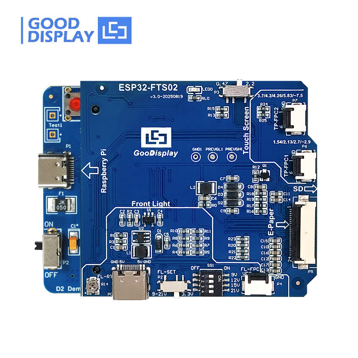
3.2 Connection Diagram
The following diagram illustrates a typical connection of the GDEQ0426T82-FT01C display module to a demo board, highlighting key connection points and jumper settings for the front light.

3.3 Recommended Driver Boards
For ease of development and integration, goodisplay offers matching driver boards:
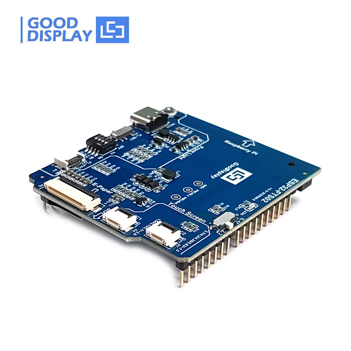
- ESP32-FTS02 (Adapter Board for Front Light & Touch Screen): A high-performance adapter board integrating power management, level conversion, and signal conditioning for a plug-and-play solution.
- ESP32-L(FTS02) (ESP32 Demo Kit with Front Light & Touch): A complete development platform with ESP32 main controller, Wi-Fi/Bluetooth, and rich example codes.
- ESP32E6-E01 (Bluetooth/WiFi/USB/SD Card Driver Board): A multi-protocol communication board suitable for IoT applications.

4. Operating Instructions
4.1 Power On/Off and DSLP Sequence
The general operation flow to drive the display panel involves the following steps:
- Power On: Supply VCI and wait for 10ms.
- Set Initial Configuration: Define the SPI interface for MCU communication, perform hardware (HW) reset, software (SW) reset (Command 0x12), and wait for 10ms.
- Send Initialization Code: Clear and fill two RAMs (Commands 0x46, 0x47), set gate driver output (Command 0x01), set display RAM size (Commands 0x11, 0x44, 0x45), and set panel border (Command 0x3C).
- Load Waveform LUT: Sense temperature (Command 0x18), load waveform LUT from OTP (Commands 0x22, 0x20) or by MCU, then wait for BUSY Low signal.
- Write Image and Drive Display Panel: Write image data to RAM (Commands 0x4E, 0x4F, 0x24, 0x26), set softstart setting (Command 0x0C), drive display panel (Commands 0x22, 0x20), then wait for BUSY Low signal.
- Power Off: Enter deep sleep mode (Command 0x10) and then power OFF the module.
4.2 SPI Interface Timing
The display module communicates via SPI. Adherence to the specified AC electrical characteristics and timing diagrams is crucial for reliable operation. The SPI timing diagram illustrates the relationship between CS#, SCL, and SDA signals during data transfer.

For detailed timing specifications, refer to the AC Electrical Characteristics table in the full product datasheet.
4.3 Touch Screen Operation
The integrated capacitive touch screen supports multi-touch input. Ensure the touch controller (FT6336U) is properly initialized and configured via the I2C interface. The touch screen operates within a voltage range of 2.8-3.6V.
4.4 Front Light Operation
The front light system uses 7 LEDs for illumination. It can be adjusted for brightness and can switch between cool/warm light modes. The front light operating voltage should be ≤15V and the operating current ≤15mA. Control of the front light is typically managed through the connected driver board.
5. Maintenance and Handling
5.1 General Handling Precautions
- Do not apply pressure to the EPD panel to prevent damage.
- Do not connect or disconnect the interface connector while the EPD panel is in operation.
- Avoid touching the IC bonding area, as it may scratch the TFT lead or damage IC function.
- Be mindful of moisture to avoid its penetration into the EPD panel, which can cause damage.
- Do not expose the unprotected EPD panel to high temperature, high humidity, sunlight, or fluorescent light for long periods, as this may degrade performance.
- Always use ESD (Electrostatic Discharge) protection when handling the display module.
- Keep the display in dry conditions to avoid moisture damage.
5.2 Cleaning the Display
- When the surface becomes dusty, wipe gently with absorbent cotton or other soft materials like chamois soaked with petroleum benzene.
- Normal-hexane is recommended for cleaning adhesives.
- Do NOT use acetone, toluene, or alcohol, as they can cause chemical damage to the PS.
- Wipe off saliva or water drops as soon as possible, as prolonged contact can cause deformations and color fading.
5.3 Environmental Requirements
- The display module should not be exposed to harmful gases, such as acid and alkali gases, which can corrode electronic components.
- Disassembling the display module can cause permanent damage and invalidate warranty agreements.
- IPA solvent can only be applied on the active area and the back of the glass; it is not allowed on other parts.
6. Troubleshooting
This section outlines common issues and their potential causes or inspection criteria.
6.1 Displaying Defects
| Item | Criteria / Description | Defect Level |
|---|---|---|
| Poor DOT SHAPE (black, white, group White) | Dots with diameter D > 0.5mm, or 0.25mm < D ≤ 0.5mm with distance < 5mm. | Major |
| Line defects | White or black lines running through the entire screen under any operation interface. | Major |
| Ghosting | Ghosts appear only during screen switching. | Major |
| Flash Point | Flash point occurs during screen switching only. | Major |
| Flash Line | Flash line occurs during screen switching only. | Major |
| Display screen error | Unable to display a fixed screen correctly. | Major |
| Display abnormal | No display, red matrix darkens, fuzzy, barcode not scanned. | Major |
| Residual image | Residual image present (visual, final judgment reference optical specification). | Major |
| Mura Anomaly | White/gray mura is not allowed. | Major |
6.2 Appearance Defects
Visual inspection should be performed to identify any physical defects. Examples include:
- Spotty defects: Black spots, white spots, foreign bodies, air bubbles, bumps.
- Linear defects: Poor linear shape, glass scratches.
- Edge breakage: Damage to the edges of the display.
- Dirt: Fingerprints, dust, residual glue.
- Silicone issues: Cracks, impurities in glue, improper coverage of ACF.
6.3 General Precautions for Operation
- Ensure the VDD and VCI inputs are stable; ripple and noise are not allowed.
- All timings for SPI communication must be strictly followed.
7. User Tips
- Power Management: Utilize the deep sleep mode (Command 0x10) when the display is not actively updating to maximize power savings, especially in battery-powered applications.
- Refresh Optimization: For applications requiring frequent updates, consider using partial refresh (0.42s) instead of full refresh (3.5s) to reduce power consumption and improve responsiveness.
- Environmental Control: To prolong the display's lifespan and maintain optimal performance, operate it within the recommended temperature and humidity ranges, and avoid direct sunlight or harsh chemicals.
- Development Kits: For new projects, consider using the recommended ESP32 demo kits (ESP32-FTS02 or ESP32-L(FTS02)) as they provide integrated solutions and example codes to accelerate development.
8. Warranty and Support
All specifications listed in this document are guaranteed for the module only. Post-assembled operation or component(s) may impact module performance or cause unexpected effects or damage, and therefore listed specifications are not warranted after any post-assembled operation.
8.1 Certifications
Our products adhere to high quality and environmental standards, including:
- ISO 14001 Environmental Management
- RoHS Compliant
- Energy Star Certified

8.2 Contact and Further Documentation
For more detailed information, including comprehensive datasheets and application notes, please refer to the relevant manual available in our Library or visit our official website. If you need any further assistance or have any other questions, please feel free to contact us. You can send your inquiries to: info@good-display.com.
The full user manual (PDF) for this product can be referenced for in-depth technical details: GDEQ0426FT82-T01C User Manual (PDF)


