
1. Introduction
The GODIAG GT100 PLUS GPT is a versatile testing platform designed for OBDII protocol communication detection and ECU maintenance, diagnosis, programming, and coding. It features a voltage and current display, which assists maintenance engineers in assessing the current operational status of the ECU. This device converts the car's OBD2 interface into a 16-pin connector for signal detection, allowing connection to single or multiple vehicle modules. It can also be used with any diagnostic tool to verify vehicle communication integrity.
Key capabilities include 24V to 12V voltage conversion, DOIP-ENET communication, and GPT functionality for reading and writing ECU data. Additionally, it can supply power to the vehicle during battery changes, preventing data loss, automatic locking, key remote control failures, and fault light activation. The product utilizes CANH and CANL shielded twisted cables to resist electromagnetic interference, ensuring more stable communication.


2. Safety Precautions
Before operating the GODIAG GT100 PLUS GPT, please read and adhere to the following safety guidelines to ensure your safety, the safety of others, and to prevent damage to the equipment and vehicles.
- Always work in a well-ventilated area, as vehicle exhaust can be harmful.
- Wear safety goggles that meet ANSI standards.
- Ensure the vehicle's gear is set to P (Park) for automatic transmissions or N (Neutral) for manual transmissions, and the parking brake is engaged.
- Keep clothing, hair, hands, and tools clear of operating engine parts and hot components.
- Place wheel chocks or bricks before each wheel to prevent accidental vehicle movement.
- The vehicle must be attended during all testing and operation.
- Exercise caution when working near ignition coils, distributor caps, ignition wires, and spark plugs, as these components can generate dangerous voltages.
- Ensure appropriate fire extinguishers (for gas/chemicals/electrical fires) are available at the work site.
- Do not plug or unplug the equipment while the ignition switch is on or the engine is running.
- Keep the equipment dry, clean, and free from oil, water, or grease. Use a clean cloth for cleaning.
- Do not operate diagnostic equipment while driving to avoid distractions and potential accidents.
- Refer to the vehicle's maintenance manual and follow all precautions strictly to prevent injury or damage to the diagnostic equipment.
- Do not place the diagnostic equipment on the vehicle's distributor, as strong electromagnetic interference (EMI) may damage the equipment.
- When replacing the battery with the GT100 PLUS GPT, do not switch on the ignition or start the vehicle.
3. Product Overview
3.1. Features
- OBDII Protocol Detector and Protocol Communication Diagnosis
- Short circuit function to forcibly activate the instrument and immobilizer
- Voltage / Current Value Display
- OBDII Display custom CAN protocol communication
- ECU Connection (single and multi-module)
- Expanded Connection capabilities
- OBD1 Diagnostic Interface Conversion to Standard OBD2
- Extension cable Function
- Power the Car When Replacing the Battery (Auxiliary Power Supply)
- GPT (General Purpose Timer) for reading and writing ECU data without disassembling
- DOIP-ENET Diagnostics for BMW, Benz, VW, Audi, Land Rover, Volvo, Geely (software not provided)
- 24V to 12V Voltage Conversion for heavy trucks
- Work with CAS4/CAS4+ Programming Test Platform
- Work with FEM/BDC Programming Test Platform
- Work with CAS1/CAS2 Mech-Key Test Platform
- Work with CAS2 CAS3 SER Semi Smart Test Platform
3.2. Model Comparison
The following table outlines the key differences between the GT100 Plus, GT100+, and GT100 models:

3.3. Device Layout
The GT100 PLUS GPT features various connectors and indicators for comprehensive diagnostic and programming tasks. Refer to the diagram below for an overview of the device layout:

- OBD2-DB15 diagnostic main cable
- DC12V interface
- Indicators (for communication protocols)
- Working voltage and current value display
- Banana plug interface
- DB25 color jumper ECU dedicated interface
- Power switch
- 12V(30) power switch (for constant 12V supply)
- 12V(15) power switch (for ignition-switched 12V supply)
3.4. OBDII Pinout and Indicator Light Meaning
The OBDII port on the GT100 PLUS GPT provides access to various communication lines. The indicator lights correspond to specific pins and their functions:

| Pin | Function | Pin | Function |
|---|---|---|---|
| 1 | Manufacturer custom | 9 | Manufacturer custom |
| 2 | SJE1850 wire <bus+> | 10 | SJE1850 wire<bus-> |
| 3 | Manufacturer custom | 11 | Manufacturer custom |
| 4 | Power grounding | 12 | Manufacturer custom |
| 5 | Signal grounding | 13 | Manufacturer custom |
| 6 | SAEJ2284 <CAN> high | 14 | SAEJ2284 <CAN> low |
| 7 | ISO9141-2 & iso, DIS4230-4K wire | 15 | ISO9141-2 & ISO/DIS 4230-4L wire |
| 8 | Manufacturer custom | 16 | Car battery positive |
3.5. DB25 Color Jumper Cable
The DB25 color jumper cable is essential for various connections, especially for ECU bench work. It allows for flexible wiring to specific pins.

Tips on Using DB25 Color Jumper Cable:
- 12V (30): Defined as car positive (+).
- 12V (15): Defined as car ignition with power supply.
- OBD 12V: Directly connected to the vehicle OBDII diagnostic port 12V.
- OBD 1.2.3.7.8.9.11.12.13: Correspondingly connected to the 1.2.3.7.8.9.11.12.13 pin port.
- REL GND and GND: Once connected, REL OUT outputs 12V vehicle battery positive electricity.
- K-LINE L-LINE: Correspondingly connected to the 7.K-LINE and 15. L-LINE port.
- CAN-H and CAN-L: Correspondingly connected to the 6.CAN-H and 14.CAN-L port.
4. Setup and Operation
4.1. OBDII Protocol Detection and Communication Status
- Connect the diagnostic/programming/coding tool to the OBD2 port of the GT100 PLUS GPT. (Do not connect it directly to the vehicle at this stage).
- Select the vehicle model and functions to operate on your diagnostic tool.
- If the diagnostic tool sends communication signals, the corresponding protocol indicators on the GT100 PLUS GPT will light up or blink. If no indicator lights up, it suggests a connection problem or a damaged device.

To check vehicle communication:
- Connect the GT100 PLUS GPT to the vehicle's OBD2 port.
- Start the Power switch on the GT100 PLUS GPT. The device will display the current accumulator voltage. If no voltage is displayed, check the vehicle diagnostic interface and cable. If the voltage is below 10V, do not start the vehicle or proceed with operations; charge the car battery first.
- Connect the diagnostic/programming/coding tool. When it communicates with the vehicle, the corresponding protocol indicators on the GT100 PLUS GPT will light up or blink, allowing you to observe which protocol the vehicle module is using and the communication status.

4.2. GPT (General Purpose Timer) Function
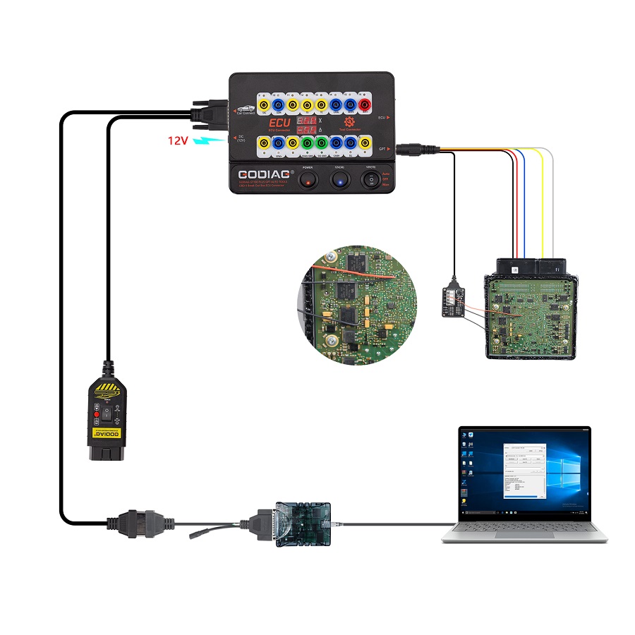
The GPT function allows reading and writing ECU data without disassembling the ECU. It supports OBD2 BENCH (CAN bus & K-Line) and GPT BOOT CNF1 protocols.
4.3. DOIP-ENET Diagnostics
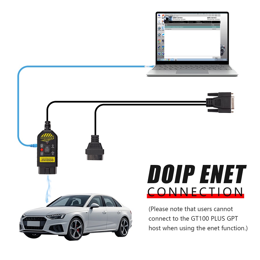
The GT100 PLUS GPT supports DOIP-ENET communication for diagnostic programming and coding on vehicles that utilize the DOIP protocol, such as BMW, Benz, Volkswagen, Audi, Land Rover, Volvo, and Geely. Note that specific software for these operations is not provided with the GT100 PLUS GPT.
4.4. 24V to 12V Voltage Conversion
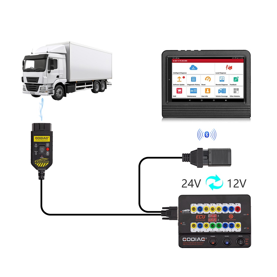
This function allows the GT100 PLUS GPT to convert the 24V voltage from diagnostic interfaces of heavy trucks, light trucks, and pickups into a 12V voltage suitable for diagnostic equipment.
4.5. ECU Connection (Single Module)
The GT100 PLUS GPT facilitates single-module ECU diagnosis and programming on the bench.
- Connect the GT100 PLUS GPT and the dedicated ECU color jumper.
- Connect the ECU module to be diagnosed or programmed, following the ECU connection definition.
- Connect the 12V DC power adapter.
- Start the Power switch on the GT100 PLUS GPT. The device will display the current working voltage of the power adapter.
- Connect the diagnostic/programming/coding tool. The GT100 PLUS GPT protocol indicator will light up or blink to show the car module's protocol and communication status.

4.6. Multi-ECU Module Connection
For scenarios requiring connection to multiple ECU modules, such as for key programming, the GT100 PLUS GPT can be configured as follows:
- Connect the GT100 PLUS GPT and the Colorful Jumper Cable DB25. Insert the DB25 jumper into the banana plug, tighten the screw, and then insert it into the corresponding port of the GT100 PLUS GPT.
- Connect the ECUs to be diagnosed or programmed, following the ECU connection definition.
- Connect the 12V DC power adapter.
- Start the Power switch on the GT100 PLUS GPT. The device will display the current working voltage of the power adapter.
- When there is good communication between the car and the diagnostic/programming/coding tool, the GT100 PLUS GPT protocol indicator will light up or blink to indicate the car module's protocol and communication status.

4.7. Key Programming (Specific Scenarios)
The GT100 PLUS GPT can assist in key programming for various vehicle brands:
- VW 4th/5th Generation (All Keys Lost): Use the GT100 PLUS GPT to short-circuit banana connector PIN 16 to PIN 1 to light up the dashboard. Then, use a key programmer tool with the female adapter of the GT100 PLUS GPT for data collection.
- Toyota (Engine ECU Replacement / All Keys Lost): Short-circuit PIN13-PIN4.
- Mitsubishi (All Keys Lost): Short-circuit PIN1-PIN4.
- Porsche Cayenne (All Keys Lost): Short-circuit PIN3-PIN7.

4.8. Auxiliary Power Supply for Battery Replacement
To prevent data loss or issues with anti-theft remote control data when replacing a vehicle battery, the GT100 PLUS GPT can provide an uninterruptible power supply.
- Prepare a spare battery (Battery A) and the new battery (Battery B) to be installed.
- Connect the GT100 PLUS GPT to pins 16, 4, and 5 of the car's OBD2 diagnostic port, and connect to Battery A.
- Switch on the GT100 PLUS GPT Power.
- Connect the GT100 PLUS GPT diagnostic cable to the OBD2 port of the vehicle. (Note: Do not turn on the ignition or start the vehicle).
- Remove the old battery and install the new Battery B.

4.9. OBD2 Cable Extension
The GT100 PLUS GPT's 1.4-meter OBD2 cable helps resolve issues where diagnostic tool cables are too short or the vehicle's diagnostic port is difficult to access. Connect the GT100 PLUS GPT first, turn on the power switch, and check the voltage display to ensure proper power supply from the vehicle.

4.10. OBD1 to OBD2 Conversion
For older OBD1 vehicles or those with special diagnostic ports, the GT100 PLUS GPT can convert the OBD1 port to a standard OBD2 diagnostic port using the banana plug and DB25 jumper.

4.11. BMW Test Platforms
The GT100 PLUS GPT supports various BMW test platforms:
- CAS1/CAS2 Mech-Key Test Platform: Used to test mechanical keys.
- CAS2 CAS3 SER Semi Smart Test Platform: Used for semi-smart key testing.
- CAS4/CAS4+ Programming Test Platform: Used to test if programmed keys work normally with CAS4.
- FEM/BDC Programming Test Platform: Used for FEM/BDC module programming.


5. Maintenance
Proper maintenance ensures the longevity and reliable operation of your GODIAG GT100 PLUS GPT.
- Cleaning: Keep the equipment dry, clean, and free from oil, water, or grease. Use a soft, clean cloth to wipe the device. Do not use abrasive cleaners or solvents.
- Storage: Store the device in a cool, dry place away from direct sunlight and extreme temperatures.
- Cable Care: Inspect all cables regularly for signs of wear, cuts, or damage. Replace damaged cables immediately to prevent electrical hazards or communication issues.
- Environmental Conditions: Avoid operating the device in environments with excessive dust, humidity, or corrosive substances.
6. Troubleshooting
This section provides solutions to common issues you might encounter while using the GT100 PLUS GPT.
- No Voltage Display / Low Voltage: If the device does not display voltage or shows a voltage below 10V, check the vehicle's OBD2 diagnostic interface and the connection cable. Ensure the vehicle battery is adequately charged. Do not proceed with diagnosis or programming if the voltage is too low, as this can lead to data loss or module damage.
- No Communication Signals: If the protocol indicators do not light up or blink when connected to a diagnostic tool or vehicle, verify all connections are secure. The issue might be a connection problem with the diagnostic tool, the GT100 PLUS GPT, or the vehicle's communication lines.
- Inconsistent Current Display / High Current: If the displayed current is inconsistent with expected values or shows excessively high current, first check all wiring for incorrect connections. If wiring is correct, it may indicate a damaged ECU module.
- Device Not Powering On: Ensure the 12V DC power adapter is correctly connected and functioning, and that the power switch on the GT100 PLUS GPT is turned on.
7. Specifications
The technical specifications for the GODIAG GT100 PLUS GPT are as follows:
| Item | Specification |
|---|---|
| Diagnostic port | OBDII 16 pin |
| Working voltage | DC 9V-24V |
| Work and power | 0.5-0.6W |
| Adapter power | Input AC100V-240V, Output DC12V 1A |
| Operating temperature range | -20 to 70 °C (-4 to 158 °F) |
| Storage temperature range | -40 to 85 °C (-40 to 185 °F) |
| Dimension | L: 23cm, W: 18cm, H: 7cm |
| Item Weight | 2kg |
| Material | Plastic |
| Certification | CE |

8. Warranty and Support
The GODIAG GT100 PLUS GPT comes with a 1-year warranty from the date of purchase.
For technical support, service, or warranty claims, please contact GODIAG using the information below:
- Website: www.godiag.com
- Phone: +86 18813687743
- Email: Sales@GoDiag.com
When contacting support, please be prepared to provide your contact name, mailing address, phone number, a complete description of the problem, and proof of purchase. You may be instructed to send the equipment to your local distributor for service.
A detailed user manual in PDF format is available for download: User Manual (PDF).
9. User Tips
- Monitor Voltage Carefully: Always pay close attention to the voltage display on the GT100 PLUS GPT. If the voltage drops below 11V during diagnosis or programming, immediately stop the operation. Continuing with low voltage can lead to critical issues like data loss, module locking, or the vehicle failing to start.
- Verify Connections: Before starting any procedure, double-check all cable connections to ensure they are secure and correctly matched to the appropriate pins. Loose or incorrect connections are a common cause of communication failures.
- Consult Vehicle Manuals: For specific vehicle procedures, always refer to the vehicle's official service or repair manual in conjunction with the GT100 PLUS GPT instructions. This ensures compatibility and adherence to manufacturer guidelines.