
1. Product Overview
The GODIAG GT100 PLUS GPT is a versatile testing platform designed for OBDII protocol communication detection, ECU maintenance, diagnosis, programming, and coding. It features a voltage and current display to monitor the ECU's working status, aiding maintenance engineers in their tasks.
This device converts the car's OBD2 interface into a 16-pin connector for signal detection, allowing connection to single or multiple vehicle modules. It can be used with any diagnostic tool to assess vehicle communication integrity.
Key features include 24V to 12V voltage conversion, DOIP-ENET communication, and GPT functionality for reading and writing ECU data. It also provides auxiliary power during battery changes to prevent data loss or module locking.
The GT100 PLUS GPT utilizes CANH and CANL shielded twisted cables to ensure stable communication by resisting electromagnetic interference.
Package Contents
The GODIAG GT100 PLUS GPT package includes the following items:
- 1 x Host Unit
- 1 x GPT Connecting Cable
- 1 x Ethernet Cable
- 1 x OBD 2-in-1 Extension Cable
- 1 x Colored Jumper Cable
- 1 x 12V Power Supply
- 1 x 120 Ohm Resistance
- 6 x Banana Plugs
- 24 x Wire Accessories (Dupont 2.54mm connector female pins)
- 1 x Operation Manual
For a visual guide to the package contents, please refer to the unboxing video below:
Video: Unboxing and overview of the GODIAG GT100 PLUS GPT and its components.

Image: GODIAG GT100 PLUS GPT with CAS adapters and various cables included in the package.
2. Setup and Connections
2.1 OBDII Interface Connection
Connect the GT100 PLUS GPT to your vehicle's OBDII diagnostic port. The device's LEDs will indicate the communication status. The built-in display shows the real-time voltage of the OBDII interface. Ensure the voltage is above 11V before proceeding with diagnosis or programming to prevent potential issues.
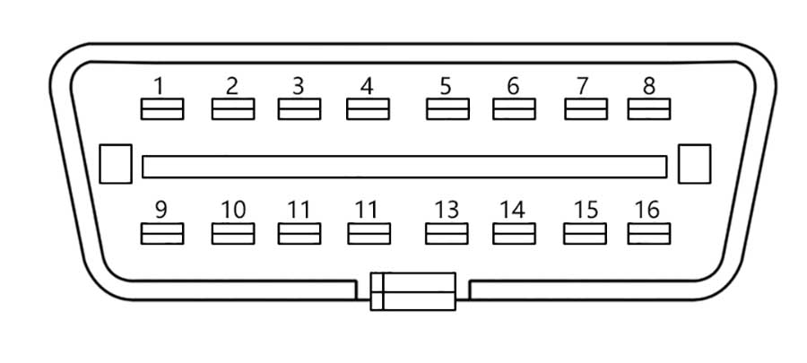
Image: Diagram showing the GT100 PLUS GPT connected to a vehicle's OBDII port and a diagnostic tool, displaying voltage and communication status.
2.2 OBDII Pinout Diagram
Understanding the OBDII pinout is crucial for proper connections and diagnostics. Refer to the diagram below for pin assignments:

Image: OBDII 16-pin connector pinout diagram with pin descriptions.
| Pin | Description | Pin | Description |
|---|---|---|---|
| 1 | Manufacturer custom | 9 | Manufacturer custom |
| 2 | SJE1850 wire | 10 | SJE1850 wire (bus-) |
| 3 | Manufacturer custom | 11 | Manufacturer custom |
| 4 | Power grounding | 12 | Manufacturer custom |
| 5 | Signal grounding | 13 | Manufacturer custom |
| 6 | SAEJ2284 CAN high | 14 | SAEJ2284 CAN low |
| 7 | ISO9141-2 & ISO/DIS 4230-4K wire | 15 | ISO9141-2 & ISO/DIS 4230-4L wire |
| 8 | Manufacturer custom | 16 | Car battery positive |
2.3 ECU Connection Modes
The GT100 PLUS GPT supports various ECU connection methods:
- Single ECU Module Connection: Connect the GT100 PLUS GPT to a single ECU module for diagnosis and programming on the bench. This method helps prevent data loss in other modules when testing directly on the vehicle.

Image: Diagram illustrating single ECU module connection with the GT100 PLUS GPT and a diagnostic tool.
- Multiple ECU Module Connection: For tasks requiring connection to multiple ECUs, such as key programming, the GT100 PLUS GPT facilitates this setup.

Image: Diagram depicting multiple ECU module connection for key programming.
- Bench Connection for Diagnostic/Programming Tools: Quickly communicate with a single ECU on the bench by connecting it with your ECU diagnostic/programming tool.

Image: Diagram showing the GT100 PLUS GPT connected to a vehicle's OBDII port and an ECU on a bench for diagnostic/programming.
2.4 Auxiliary Power Supply for Battery Replacement
To prevent data loss or anti-theft system issues when replacing a vehicle's battery, the GT100 PLUS GPT can provide an uninterruptible power supply. Connect the device to the vehicle before disconnecting the old battery to maintain power to the ECU.

Image: Diagram showing the GT100 PLUS GPT providing auxiliary power to a vehicle during battery replacement.
2.5 Extended Cable and OBD1 to OBD2 Conversion
The GT100 PLUS GPT's 1.4-meter OBD2 cable addresses issues with short diagnostic tool cables or narrow vehicle diagnostic ports. For older OBD1 vehicles or special diagnostic ports, use the banana plugs and DB25 jumper to convert them to a standard OBD2 diagnostic port.

Image: Diagram showing the GT100 PLUS GPT connected to a vehicle's OBDII port and a diagnostic tablet, highlighting the extended cable length.

Image: Diagram illustrating the conversion of an OBD1 port from a special truck to a standard OBD2 port using the GT100 PLUS GPT.
3. Operating Instructions
3.1 GPT Functionality
The GT100 PLUS GPT supports GPT (General Purpose Timer) connection methods to read and write ECU data without disassembling the ECU. It supports OBD2 BENCH (CAN bus & K-Line) and GPT BOOT CNF1 protocols.
3.2 DOIP-ENET Diagnostics
The device supports DOIP-ENET communication for diagnostic programming and coding. This is applicable for BMW, Benz, Volkswagen, Audi, Land Rover, VOLVO, and Geely vehicles that support the DOIP protocol. (Note: Software for these specific vehicle brands is not provided with the GT100 PLUS GPT.)
3.3 24V to 12V Voltage Conversion
The GT100 PLUS GPT can convert the 24V diagnostic interface voltage of heavy trucks, light trucks, and pickups to 12V, making it compatible with standard diagnostic equipment.
3.4 Communication Signal Check
Use the GT100 PLUS GPT to verify if your diagnostic, programming, or coding tool is sending communication signals correctly.
3.5 Key Programming Scenarios
The GT100 PLUS GPT assists in various key programming scenarios:
- VW 4th/5th Generation All Keys Lost: For vehicles like A6L, Touareg, A4, Q5, A7, use the GT100 PLUS GPT to short-circuit banana connector PIN 16 to PIN 1 to illuminate the dashboard. Then, connect your key programmer tool to the female adapter of the GT100 PLUS GPT for data collection. Note that some dashboards may not light up, but data collection can still proceed (e.g., A6L Q7).
- Toyota Engine ECU Replacement / All Keys Lost: Short-circuit PIN 13 to PIN 4.
- Mitsubishi All Keys Lost / OBDII Setup: Short-circuit PIN 1 to PIN 4.
- Porsche Cayenne All Keys Lost: Short-circuit PIN 3 to PIN 7.
3.6 CAS1/CAS2/CAS3/CAS4 Test Platforms
The GT100 PLUS GPT works with CAS1/CAS2 Mech-Key Test Platforms and CAS2 CAS3 SER Semi Smart Test Platforms. It is also used with the BMW CAS4/CAS4+ Programming Test Platform to verify programmed keys.

Image: Diagram of the GT100 PLUS GPT connected to a BMW CAS4/CAS4+ Programming Test Platform and a laptop for key testing.
3.7 BMW FEM/BDC Programming Test Platform
The device supports connection to the BMW FEM/BDC Programming Test Platform for advanced programming tasks.

Image: Diagram of the GT100 PLUS GPT connected to a BMW FEM/BDC Programming Test Platform and a laptop.
4. Specifications
| Item | Specification |
|---|---|
| Diagnostic Port | OBDII |
| Working Voltage | DC 9V-24V |
| Work and Power | 0.5-0.6W |
| Adapter Power | Input AC100V-240V, Output DC12.5V 2.5A |
| Operating Temperature Range | -20 to 70 °C (-4 to 158 °F) |
| Storage Temperature Range | -40 to 85 °C (-40 to 185 °F) |
| Dimension (L x W x H) | 23cm x 18cm x 7cm |
| Item Weight | 1.3kg |
| Material | Plastic |
5. Maintenance
To ensure the longevity and optimal performance of your GODIAG GT100 PLUS GPT, follow these maintenance guidelines:
- Keep the device clean and free from dust and debris. Use a soft, dry cloth for cleaning.
- Store the device in a cool, dry place away from direct sunlight and extreme temperatures.
- Avoid dropping or subjecting the device to strong impacts.
- Regularly inspect cables and connectors for any signs of wear or damage. Replace damaged components immediately.
- Do not attempt to open or repair the device yourself, as this may void the warranty and cause further damage. Refer to qualified service personnel for repairs.
6. Troubleshooting
- No Power/Display: Ensure the 12V power supply is correctly connected and functioning. Check all cable connections.
- Communication Issues: Verify that the OBDII interface voltage displayed on the GT100 PLUS GPT is above 11V. If it is below 11V, stop diagnosis/programming to prevent data loss or module locking. Check for proper pin connections according to the OBDII pinout diagram.
- Device Not Recognized by Diagnostic Tool: Ensure all connections are secure. Confirm that the diagnostic tool is compatible with the vehicle's protocol and the GT100 PLUS GPT's capabilities.
- Risk of Burning Diagnostic Tool: Always connect the GT100 PLUS GPT first and check the voltage display before connecting your diagnostic tool, especially if the vehicle's OBD2 port may have been modified. This helps prevent damage to your diagnostic equipment.
7. User Tips
- Confirm Included Components: The GODIAG GT100 PLUS GPT package includes the main GT100 PLUS unit along with CAS adapters (CAS1/CAS2 and CAS3/CAS4) as depicted in the product images.
- Voltage Monitoring: Always pay attention to the voltage display on the GT100 PLUS GPT. A stable voltage (above 11V) is critical for successful and safe ECU operations.
- Bench Work: Utilize the bench connection capabilities for single or multiple ECU modules to perform diagnostics and programming in a controlled environment, minimizing risks to the vehicle's other systems.
- Cable Management: The extended OBD2 cable provides flexibility. Ensure it is routed safely and does not interfere with vehicle operation or other equipment during use.
8. Warranty and Support
For detailed warranty information, technical support, and further documentation, please refer to the official user manual PDF provided by the manufacturer. A digital version of the user manual can be accessed via the following link: GODIAG GT100 PLUS GPT User Manual (PDF).