1. Introduction
This manual provides detailed instructions for the TZT 10G Frequency Mixer Module, which integrates an LMX2594-PLL local oscillator and an STM32 main control board. This module is designed for both up and down frequency conversion applications, covering a wide range of RF, LO, and LF frequencies.
2. Specifications
| Feature | Value |
|---|---|
| Brand Name | TZT |
| Model Number | Frequency Mixer Module (LMX2594-PLL) |
| RF and LO Frequency Range | 4G - 10GHz |
| LF Frequency Range | DC-4GHz |
| Core Chip for Local Oscillator | LMX2594 |
| Control Board | STM32 Main Control Board |
| Power Supply | Type-C Charging (5V) |
| Display | 1.3-inch TFT Display |
2.1 IF Output Amplitude (Example for 1GHz IF)
The following table illustrates the typical IF output amplitude for a 1GHz IF frequency, given various RF input frequencies and using the LMX2594 provided LO.
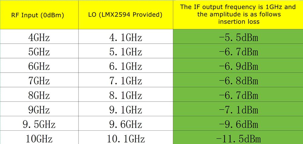
Table: IF Output Frequency (1GHz) and Amplitude (Insertion Loss) for various RF Input and LO Frequencies.
3. Package Contents
Ensure all items are present in the package:
- 1 x TZT Frequency Mixer Module
- 1 x STM32 Main Control Board
- 1 x USB Type-C Charging Cable (typically included, as seen in product images)

Image: TZT Frequency Mixer Module with included USB-C cable.
4. Setup and Connections
The TZT Frequency Mixer Module is designed for flexible integration into RF systems. Below are the key components and their connections:
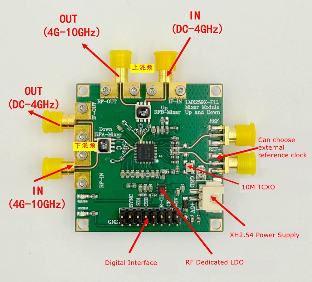
Image: Top-down view of the module with labeled ports for RF, IF, LO, power, and digital interface.
- Power Supply: Connect a 5V power source via the Type-C port or the XH2.54 Power Supply header.
- RF Input/Output:
- Down Conversion: RF Input (4G-10GHz) connects to the 'RF-IN' port. IF Output (DC-4GHz) is available at the 'IF-OUT' port.
- Up Conversion: LF Input (DC-4GHz) connects to the 'IF-IN' port. RF Output (4G-10GHz) is available at the 'RF-OUT' port.
- Local Oscillator (LO): The module has a built-in LMX2594 LO. An external reference clock can be chosen via a dedicated pin.
- Digital Interface: A digital interface (labeled 'Digital Interface') is available for control, likely for the STM32 main control board. This includes pins for SYNC, CSB, SCK, and GND.
- Buttons: The module features several buttons (S2, S3, S4, S5, S6) for control and configuration, along with an 'OFF' button.
4.1 System Block Diagram
The functional block diagram illustrates the signal flow and core components of the mixer module.
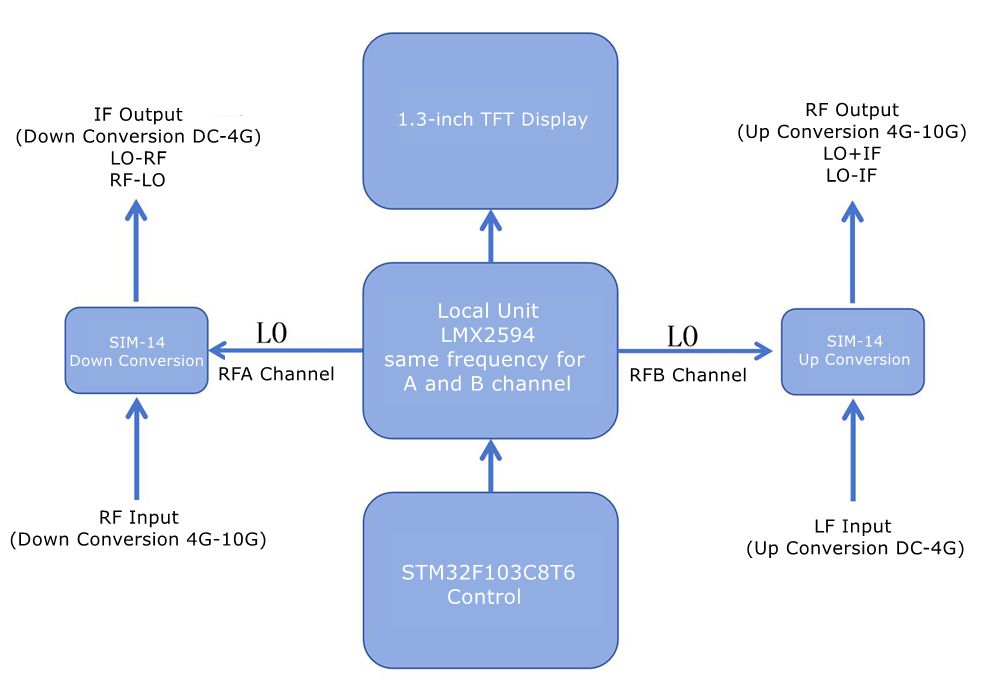
Image: Block diagram of the TZT Frequency Mixer Module, detailing the LMX2594 Local Unit, SIM-14 Up/Down Conversion blocks, 1.3-inch TFT Display, and STM32F103C8T6 Control.
5. Operating Instructions
The module is controlled via the integrated STM32 main control board and the onboard buttons, with feedback provided by the 1.3-inch TFT display.

Image: Front view of the TZT Frequency Mixer Module, highlighting the 1.3-inch TFT display and control buttons (S2, S3, S4, S5, S6, OFF).
5.1 Basic Operation
- Power On: Connect the module to a 5V power source using the Type-C cable. The TFT display should illuminate.
- Frequency Setting: Use buttons S2, S3, S4, S5, S6 to navigate menus and adjust frequency parameters for RF, LO, and IF as displayed on the TFT screen. Specific button functions (e.g., up/down, select, enter) will be indicated on the display or require experimentation.
- Mode Selection: The module supports both up and down conversion. Select the desired mode through the control interface.
- Signal Connection: Connect your RF input/output and LF input/output to the appropriate SMA connectors as described in the "Setup and Connections" section.
5.2 Up Conversion
For up conversion, the module mixes a lower frequency (LF) signal with the local oscillator (LO) to produce a higher frequency (RF) output.
- LF Input: Connect your DC-4GHz signal to the 'IF-IN' port.
- RF Output: The resulting 4G-10GHz signal will be available at the 'RF-OUT' port.
- Frequency Relationship: RF Output = LO Frequency + LF Input or LO Frequency - LF Input (depending on configuration).
5.3 Down Conversion
For down conversion, the module mixes a higher frequency (RF) signal with the local oscillator (LO) to produce a lower frequency (IF) output.
- RF Input: Connect your 4G-10GHz signal to the 'RF-IN' port.
- IF Output: The resulting DC-4GHz signal will be available at the 'IF-OUT' port.
- Frequency Relationship: IF Output = RF Input - LO Frequency or LO Frequency - RF Input (depending on configuration).
6. Maintenance
- Cleaning: Use a soft, dry cloth to clean the module. Avoid using liquids or abrasive cleaners.
- Storage: Store the module in a dry, dust-free environment when not in use.
- Handling: Handle the module with care to avoid damaging the SMA connectors or the PCB. Avoid static discharge.
- Firmware Updates: Check the manufacturer's website for any available firmware updates for the STM32 control board. Follow specific instructions provided with the update.
7. Troubleshooting
| Problem | Possible Cause | Solution |
|---|---|---|
| Module does not power on | No power, faulty cable, or power supply issue. | Ensure 5V power is connected correctly via Type-C. Try a different cable or power adapter. |
| No signal output | Incorrect frequency settings, wrong port connection, or input signal issue. | Verify RF/LO/IF frequencies are set correctly on the display. Check all cable connections to the correct IN/OUT ports. Ensure input signal is present and within specified range. |
| Display shows error message | Internal error or invalid parameter setting. | Refer to the specific error code (if any) on the display. Try resetting the module (power cycle). Reconfigure settings. |
| Buttons unresponsive | Module frozen or hardware issue. | Power cycle the module. If the issue persists, contact support. |
8. User Tips
- For optimal performance, ensure all SMA connections are tight and use high-quality RF cables.
- When experimenting with frequency settings, make small adjustments and observe the output to understand the module's behavior.
- Consider using external attenuators or amplifiers if your input/output signal levels are outside the module's optimal operating range.
9. Warranty and Support
For technical support, warranty claims, or further assistance, please contact the manufacturer or your point of purchase. Keep your purchase receipt as proof of purchase.
A user manual in PDF format is available for download: Download User Manual (PDF)


