1. Introduction
This manual provides detailed instructions for the Waveshare 0.96inch OLED Module. This compact display features a 128x64 pixel resolution and is driven by the SSD1315 chip. It offers flexible communication options, supporting both 4-wire SPI and I2C interfaces, making it compatible with various microcontrollers like Raspberry Pi, Arduino, and STM32.
Key features include an ultra-narrow bezel, compact size, and an onboard voltage translator for ease of integration into 3.3V or 5V systems.

Overview of the 0.96inch OLED Module.
2. Package Contents
The standard package for the 0.96inch OLED Module includes the following items:
- 0.96inch OLED Module x1
- Jumper cable female-female 7PIN x1

Contents of the 0.96inch OLED Module package.
3. Specifications
| Feature | Description |
|---|---|
| Operating Voltage | 3.3V / 5V |
| Display Panel | OLED |
| Resolution | 128 × 64 pixels |
| Pixel Size | 0.15 × 0.15 mm |
| Communication Interface | 4-wire SPI / I2C |
| Driver IC | SSD1315 |
| Display Size | 21.74 × 11.18 mm |
| Module Size | 26.00 × 26.00 mm |
| Display Color Options | (C): upper yellow & lower blue; (D): white; (E): blue |
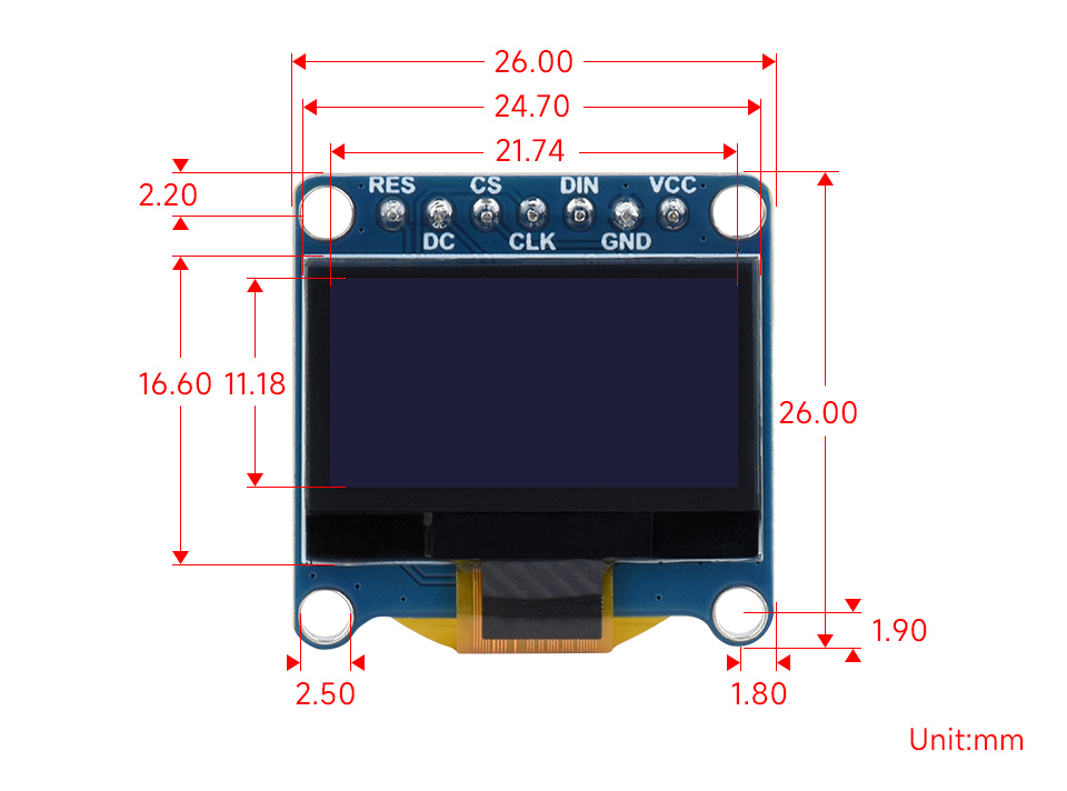
Outline dimensions of the 0.96inch OLED Module.
4. Pinout and Control Interface
The module features a 7-pin header for connecting to your microcontroller. The pin definitions are as follows:
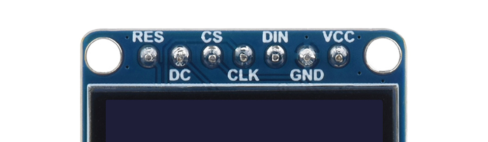
Pinout of the 0.96inch OLED Module.
| Pin | Function |
|---|---|
| RES | Reset, active low |
| DC | Data/Command selection (high for data, low for command) |
| CS | Chip selection, active low |
| CLK | Clock input |
| DIN | Data input |
| GND | Ground |
| VCC | Power (3.3V / 5V input) |
5. Setup and Hardware Connection
The 0.96inch OLED Module supports both SPI and I2C communication. Below are common wiring diagrams for connecting the module to popular development boards using the SPI interface.
5.1. Connecting with Raspberry Pi via SPI Interface
Follow the diagram below to connect the OLED module to a Raspberry Pi board using the SPI interface. Ensure correct pin mapping for VCC, GND, DIN, CLK, CS, DC, and RES.
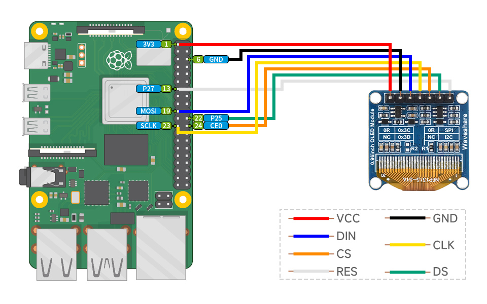
SPI connection diagram for Raspberry Pi.
5.2. Connecting with Arduino Board via SPI Interface
Refer to the diagram below for connecting the OLED module to an Arduino board using the SPI interface. Pay close attention to the pin assignments for VCC, GND, DIN, CLK, CS, DC, and RES.
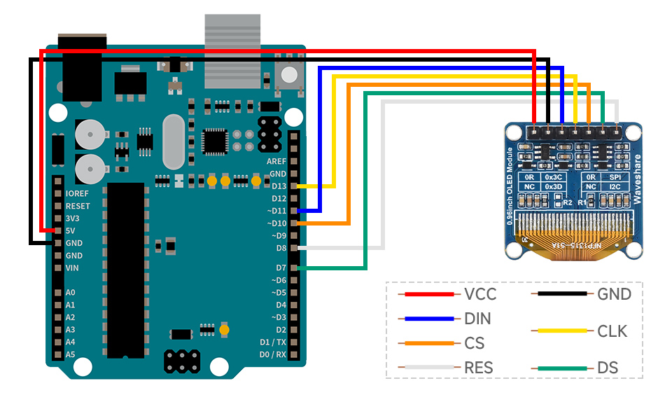
SPI connection diagram for Arduino.
6. Operating Instructions
Once connected, the OLED module can be programmed to display various text and graphics. Waveshare provides online development resources, including example code for Raspberry Pi, Arduino, and STM32, to help you get started.
The module supports different display color configurations:
- (C) Variant: Upper yellow and lower blue display blocks.
- (D) Variant: White display.
- (E) Variant: Blue display.
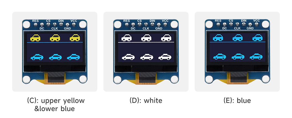
Different display color options for the 0.96inch OLED Module.
An example of the module in operation, displaying time and text, is shown below:
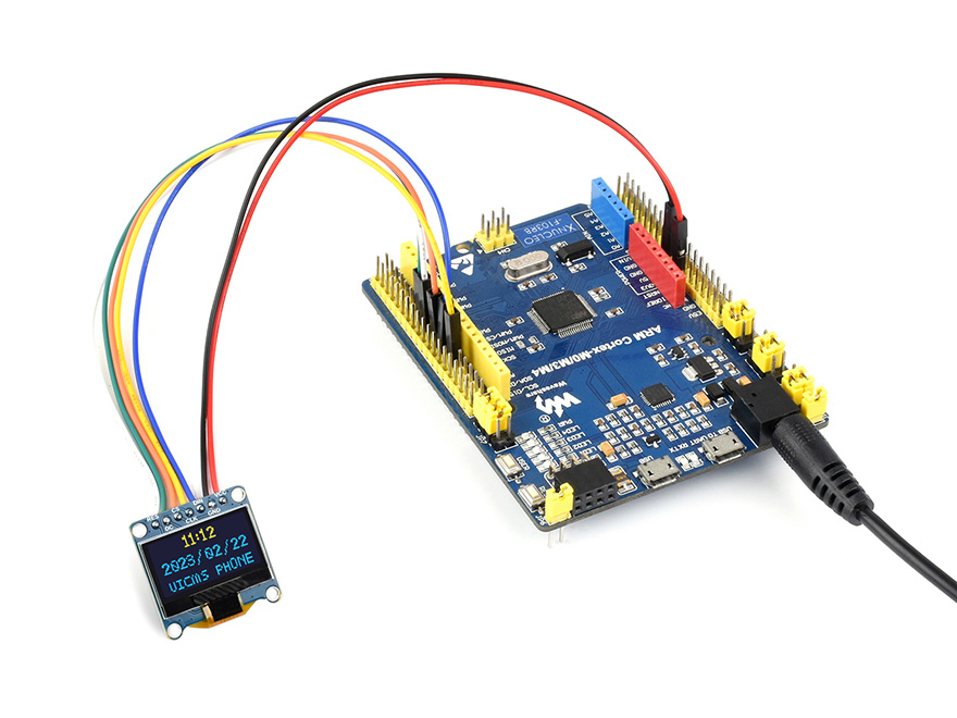
Usage example with an STM32 board (STM32 board not included).
7. Warranty and Support
For technical support, documentation, and further resources, please refer to the official Waveshare website or contact their customer service. Detailed examples and libraries for various platforms (Raspberry Pi, Arduino, STM32) are typically available in the online development resources.


