
1. Introduction
The 9IMOD F405 Flight Stack is a high-performance flight control system designed for FPV racing drones. It integrates an F405 Flight Control unit with either a 55A or 60A 4-in-1 Electronic Speed Controller (ESC). This stack features an open-source Betaflight Flight Controller, high-configuration components, and supports various signal protocols and open-source firmware, making it versatile for different FPV setups.

Figure 1: F405 Flight Control and 55A/60A ESC boards.
2. Safety Information
- Always disconnect power before handling or making any connections to the flight stack.
- Ensure correct polarity when connecting power to avoid damage to components.
- Soldering should be performed by experienced individuals. Use appropriate safety gear.
- Keep the flight stack away from moisture, dust, and extreme temperatures.
- Verify all connections and configurations before powering on your drone.
- This product is intended for users aged 14 and above.
3. Package Contents
The package typically includes the following components:

Figure 2: Package contents for F405 Flight Control + 55A ESC variant.
- F405 Flight Controller (x1)
- 4-in-1 ESC (55A or 60A, x1)
- Package Box (x1)
- TS100 GPS Connect Cable (x1)
- ESC Connect Cable (x1)
- R8SM Receiver Connect Cable (x1)
- Analog Video Transmission Connect Cable (x1)
- Camera Connect Cable (x1)
- ELRS Receiver Connect Cable (x1)
- Power cable + XT60 (x1)
- Low ESR capacitor (x1)
- Silicone vibration absorber (x8)
- Screw (x4)
- Hex nut (x4)
4. Product Overview and Features
The F405 Flight Stack offers a robust solution for FPV drone enthusiasts, featuring:
- Flight Controller (FC):
- Open-source Betaflight Flight Controller.
- High-configuration components: STM32F405RGT6 master chip, ICM42688 gyroscope, BMP280 barometer.
- Built-in OSD module for easy parameterization.
- 4 available UART ports for peripheral connectivity.
- Dual BEC setup with 5V and 12V outputs.
- Supports connectivity to all DJI Air Units.
- Standard sockets and large solder pads for convenient wiring.
- Electronic Speed Controller (ESC):
- Available in 55A or 60A continuous current variants.
- Equipped with a TVS transient suppression diode for enhanced surge voltage protection.
- Utilizes high-performance MOS for good current resistance, durability, and stability.
- High-performance processor supporting DSHOT600 protocol.
- Supports BlueJay firmware and bidirectional DSHOT.
- General:
- Supports multiple signal protocols: DSM, SBUS, TBS Crossfire, ELRS.
- Compatible with multiple open-source firmware: ArduPilot, Betaflight, INAV.
5. Specifications
5.1 F405 Flight Control Specifications
| Feature | Detail |
|---|---|
| Master Chip | STM32F405RGT6 |
| Gyroscope | ICM42688 |
| Battery Input | 3-8S Lipo |
| USB Port | Type-C |
| Barometer | BMP280 |
| OSD Chip | AT7456E |
| Bluetooth | Not Supported |
| RSSI Support | Yes (marked as RSSI) |
| Supported FC Firmware | Betaflight |
| Firmware Name | DAKEFPVF405 |
| Installation Hole Position | 30.5x30.5mm/M4 |
| Size | 36mm x 36mm x 8mm |
| Weight (Bare Board) | 8g |
5.2 55A 4-in-1 ESC Specifications
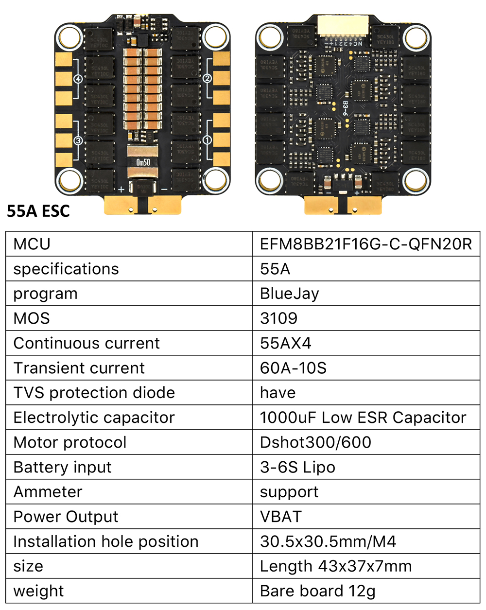
Figure 3: 55A 4-in-1 ESC Specifications.
| Feature | Detail |
|---|---|
| MCU | EFM8BB21F16G-C-QFN20R |
| Specifications | 55A |
| Program | BlueJay |
| MOS | 3109 |
| Continuous Current | 55AX4 |
| Transient Current | 60A-10S |
| TVS Protection Diode | Yes |
| Electrolytic Capacitor | 1000uF Low ESR Capacitor |
| Motor Protocol | Dshot300/600 |
| Battery Input | 3-6S Lipo |
| Ammeter | Support |
| Power Output | VBAT |
| Installation Hole Position | 30.5x30.5mm/M4 |
| Size | Length 43x37x7mm |
| Weight (Bare Board) | 12g |
5.3 60A 4-in-1 ESC Specifications
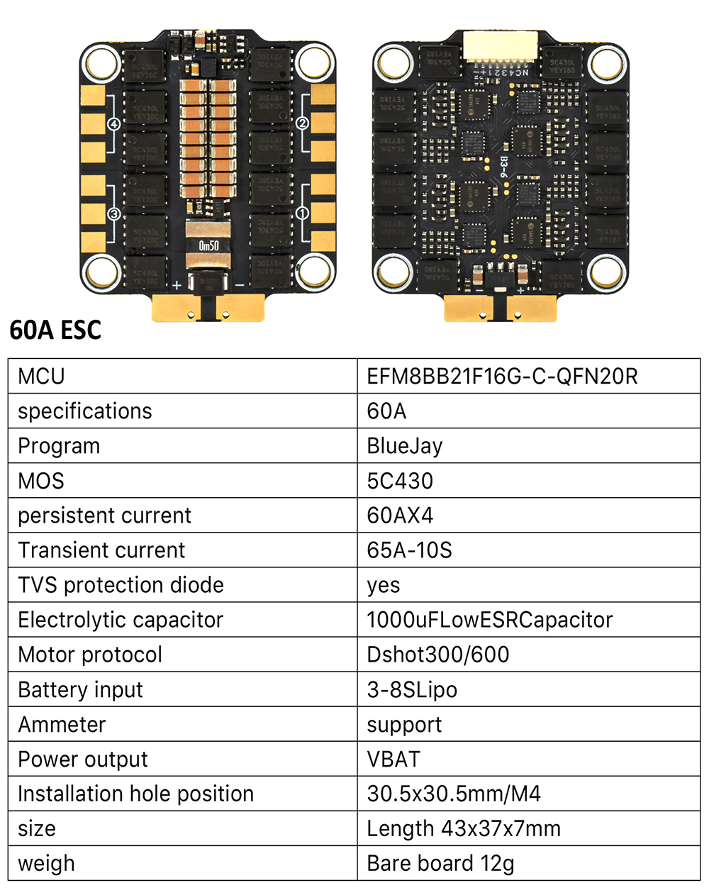
Figure 4: 60A 4-in-1 ESC Specifications.
| Feature | Detail |
|---|---|
| MCU | EFM8BB21F16G-C-QFN20R |
| Specifications | 60A |
| Program | BlueJay |
| MOS | 5C430 |
| Continuous Current | 60AX4 |
| Transient Current | 65A-10S |
| TVS Protection Diode | Yes |
| Electrolytic Capacitor | 1000uF Low ESR Capacitor |
| Motor Protocol | Dshot300/600 |
| Battery Input | 3-8S Lipo |
| Ammeter | Support |
| Power Output | VBAT |
| Installation Hole Position | 30.5x30.5mm/M4 |
| Size | Length 43x37x7mm |
| Weight (Bare Board) | 12g |
6. Setup and Installation
This section provides guidance for connecting the F405 Flight Control and ESC to your FPV drone components. Refer to the wiring diagrams carefully.
6.1 Basic Wiring Diagram

Figure 5: Basic wiring for F405 Flight Control, including Crossfire Nano Rx, Camera, ESC, VTX, and GPS.
- ESC Connection: Connect the 4-in-1 ESC to the flight controller using the provided ESC Connect Cable. Ensure the signal wires (S1-S4) and ground/power wires are correctly aligned.
- Receiver Connection: Connect your receiver (e.g., Crossfire Nano Rx, SBUS, ELRS) to the appropriate UART port on the flight controller. Refer to the diagram for specific pinouts (e.g., RX3, TX3 for Crossfire Nano Rx).
- Camera Connection: Connect your FPV camera to the CAM input and GND/5V pads.
- Video Transmitter (VTX) Connection: Connect your VTX to the VTX pads, ensuring correct video signal, power (5V or 12V), and ground connections. If using digital image transmission with BBUS control protocol, short-circuit the solder pad jumper as indicated in the diagram.
- GPS Module: Connect the GPS module to the designated UART port (e.g., TX4, RX4).
6.2 Comprehensive Wiring Diagram
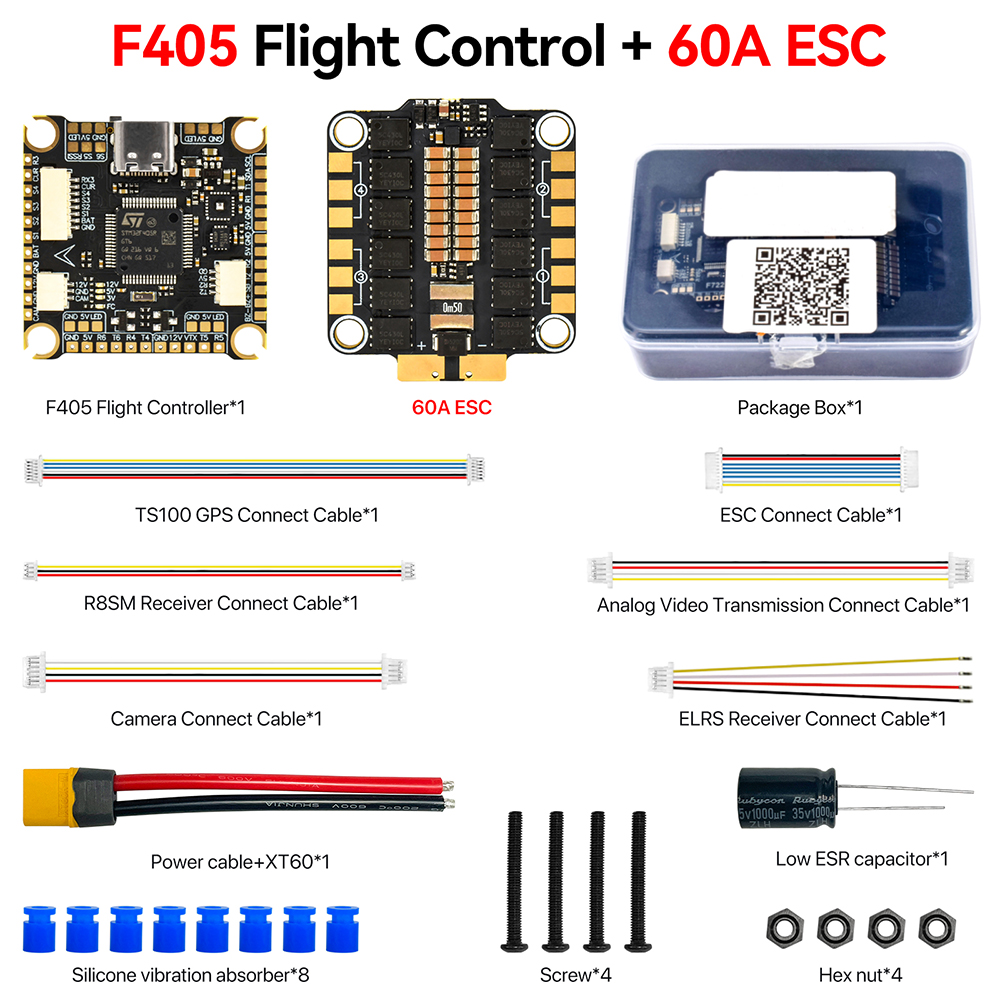
Figure 6: Comprehensive wiring diagram for F405 Flight Control with various peripherals.
- Motor Connections: Connect the four motors to the 4-in-1 ESC. Ensure motor numbering and rotation direction are correct according to your frame and flight controller software configuration.
- LEDs: Connect LED strips to the dedicated LED pads.
- Servo: If using a servo, connect it to the designated SERVO pad.
- Buzzer: Connect a buzzer to the BUZZER pads for audible alerts.
- Power Input: Connect your main battery (3-8S Lipo) to the BAT+ and BAT- pads on the ESC. The flight controller will draw power from the ESC.
- Solder Pads: The flight controller features large solder pads, making connections easier, especially for beginners.
Important: Always double-check all connections before applying power to prevent damage to components.
7. Operating Instructions
The 9IMOD F405 Flight Stack is designed to work with popular open-source firmware.
- Flight Controller Firmware: The F405 Flight Control supports Betaflight firmware. You will need to flash the DAKEFPVF405 target firmware using the Betaflight Configurator.
- ESC Firmware: The 4-in-1 ESC supports BlueJay firmware. Ensure your ESCs are flashed with the correct BlueJay firmware for optimal performance and bidirectional DSHOT functionality.
- Configuration: Use the Betaflight Configurator software to configure your flight controller settings, including PID tuning, motor outputs, receiver setup, OSD elements, and other flight parameters. The built-in OSD module allows for one-step parameterization directly from your FPV goggles.
- Motor Protocol: The ESC supports Dshot300/600 motor protocols. Configure this in your Betaflight settings.
- Signal Protocols: The flight controller supports various receiver signal protocols such as DSM, SBUS, TBS Crossfire, and ELRS. Select the appropriate protocol in your Betaflight receiver tab.
- Alternative Firmware: In addition to Betaflight, the F405 Flight Control also supports other open-source firmware like ArduPilot and INAV, offering flexibility for advanced users.
8. Maintenance
- Regular Inspection: Periodically inspect all solder joints and connections for any signs of wear, corrosion, or damage.
- Cleaning: Keep the flight stack clean from dust, dirt, and debris. Use a soft brush or compressed air. Avoid using liquids directly on the electronics.
- Firmware Updates: Regularly check for and apply firmware updates for both the flight controller (Betaflight) and ESC (BlueJay) to benefit from performance improvements and bug fixes.
- Physical Protection: Ensure the flight stack is properly mounted and protected within your drone frame to minimize vibration and impact damage. Use the provided silicone vibration absorbers.
9. Troubleshooting
- No Power/No Lights:
- Check main battery connection and polarity.
- Inspect for any short circuits or damaged wires.
- Motors Not Spinning/Erratic Behavior:
- Verify ESC connections to motors and flight controller.
- Ensure ESC firmware is correctly flashed and configured (e.g., DSHOT protocol).
- Check motor direction in Betaflight Configurator.
- Calibrate ESCs if necessary (refer to BlueJay documentation).
- No Receiver Input:
- Confirm receiver is powered and bound to your radio.
- Check receiver wiring to the flight controller (signal, ground, power).
- Verify the correct serial protocol (e.g., SBUS, CRSF) is selected in Betaflight.
- OSD Not Displaying:
- Ensure camera and VTX are correctly connected and powered.
- Check OSD settings in Betaflight Configurator.
- Flight Controller Not Connecting to PC:
- Try a different USB cable and port.
- Install necessary USB drivers (e.g., STM32 Virtual COM Port Driver, Zadig for DFU mode).
- Ensure Betaflight Configurator is up to date.
10. User Tips
- INAV Support: For those preferring INAV, this flight controller is compatible. Ensure you flash the appropriate INAV firmware target for the F405.
- Soldering Ease: The large solder pads on the flight controller are designed to simplify soldering, especially for those new to building FPV drones. Take advantage of this feature for cleaner and more reliable connections.
- TVS Diode Protection: The ESC includes a TVS transient suppression diode. While this provides enhanced protection against voltage spikes, always use a low ESR capacitor on the main battery input for additional filtering and stability.
11. Warranty and Support
Please note that this product typically does not come with an explicit warranty. In case you receive a defective item, it is recommended to contact the seller immediately with pictures or videos of the issue. They may be able to provide assistance or a resolution.
For technical support regarding firmware configuration (Betaflight, BlueJay, ArduPilot, INAV), refer to the official documentation and community forums for these open-source projects. These resources offer extensive guides and troubleshooting tips.