1. Introduction
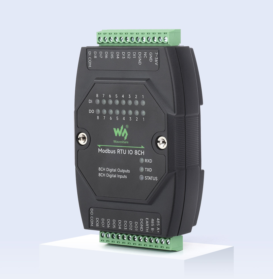
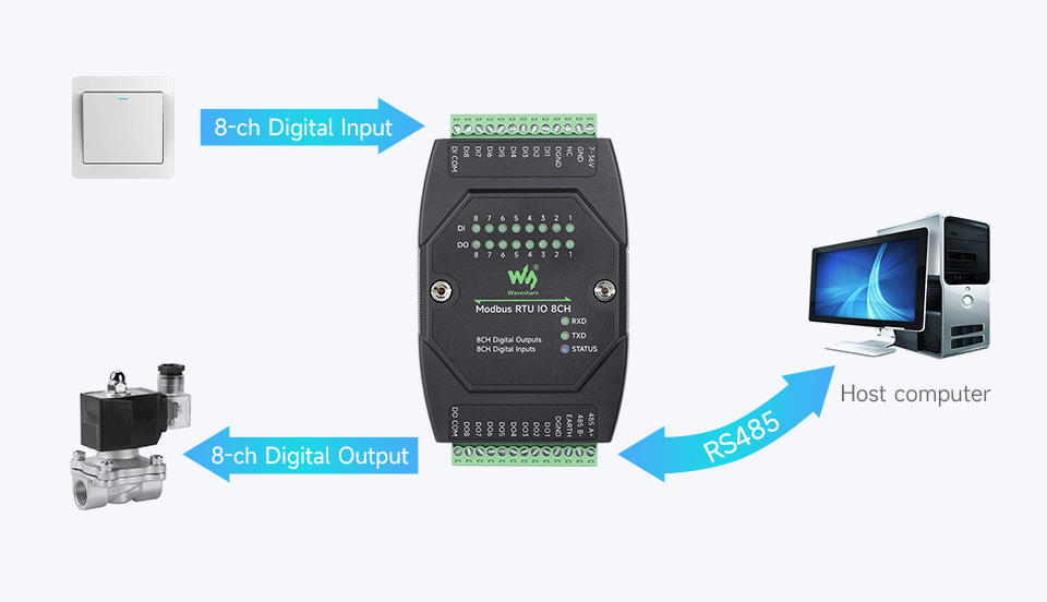
The Waveshare Modbus RTU IO 8CH is an industrial-grade 8-channel digital isolated input and 8-channel digital output module. It features an RS485 control interface and supports the Modbus RTU protocol. Designed for robust industrial applications, it incorporates various protection circuits including power isolation, magnetic isolation, resettable fuses, and Transient Voltage Suppressors (TVS) to ensure high reliability and strong anti-interference performance.

2. Package Contents
The package includes the following items:
- 1x Modbus RTU IO 8CH Module
- 1x Power supply terminal adapter
- 1x Screwdriver
3. Features
- Configurable Device Address: Supports addresses from 1 to 255, allowing multiple devices to be cascaded on an RS485 bus.
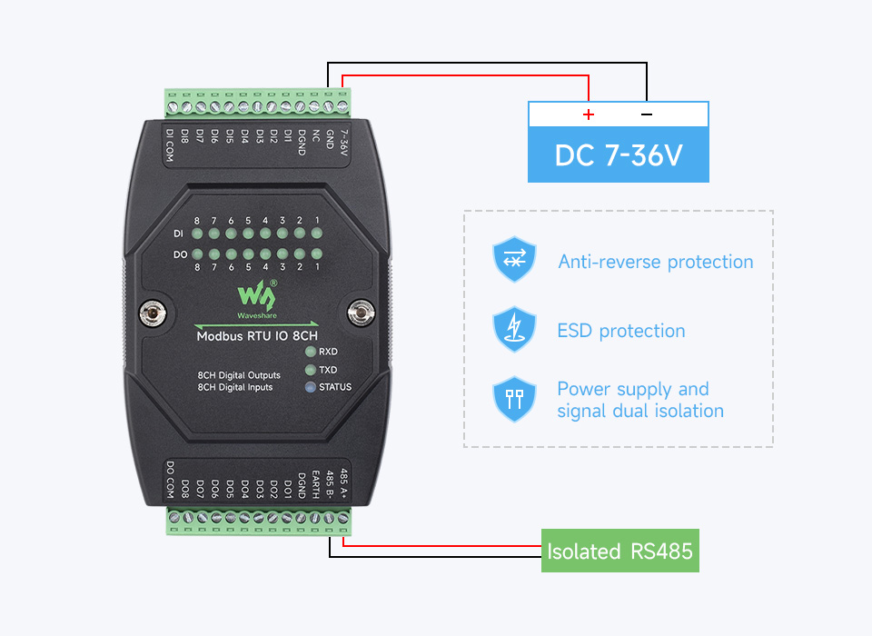
- Wide Voltage Power Supply: Onboard voltage regulator supports a DC 7~36V wide range power input.
- Power Supply Isolation: Unibody power supply isolation provides stable isolated voltage, eliminating the need for an extra power supply for the isolated terminal.
- Magnetic Isolation: Unibody magnetic isolation ensures signal isolation, high reliability, and strong anti-interference capabilities.
- Robust Protection Circuits: Includes resettable fuses and TVS (Transient Voltage Suppressor) to effectively suppress surge voltage and transient spike voltage, offering over-current/over-voltage protection, lightning protection, and anti-electrostatic properties.
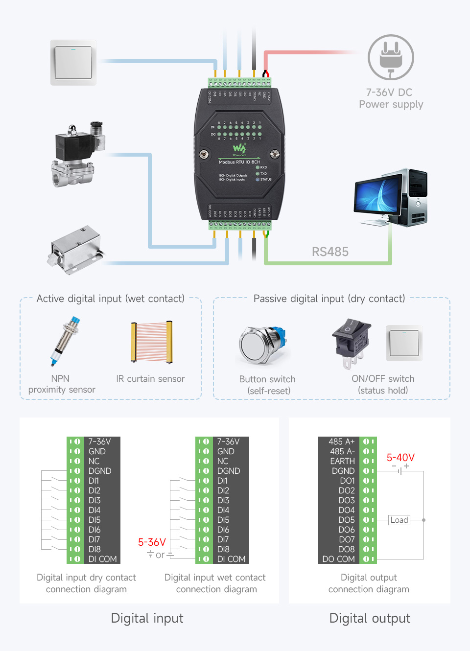
- Digital Input Flexibility: Supports passive and active digital input (NPN or PNP type) with bi-directional optocoupler isolation and a built-in debouncing algorithm. Supports DI/DO linkage control or DO toggle control.
- High-Current Digital Output: Output utilizes Darlington transistors with optocoupler isolation, providing stronger driving capability with up to 500mA sinking current per channel, suitable for directly driving relays. Built-in flyback diode protection is included.
- Flash-On/Flash-Off Function: Allows temporary activation or deactivation of outputs for a specified duration by passing arguments to commands.
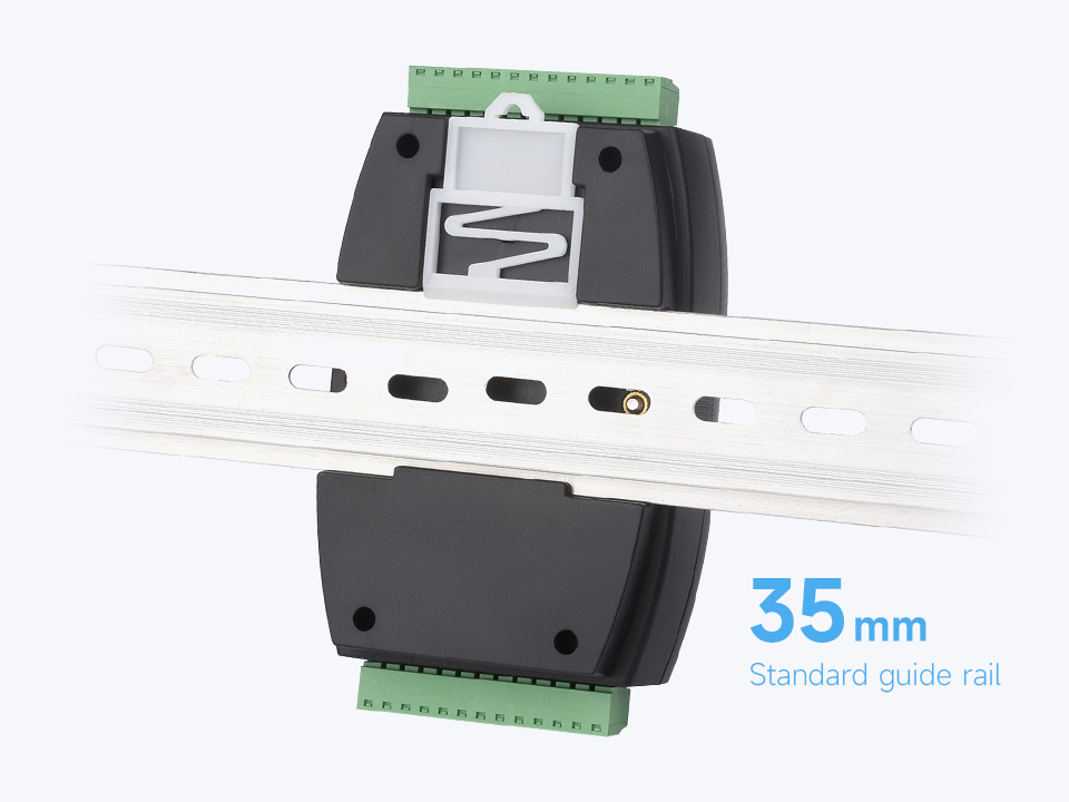
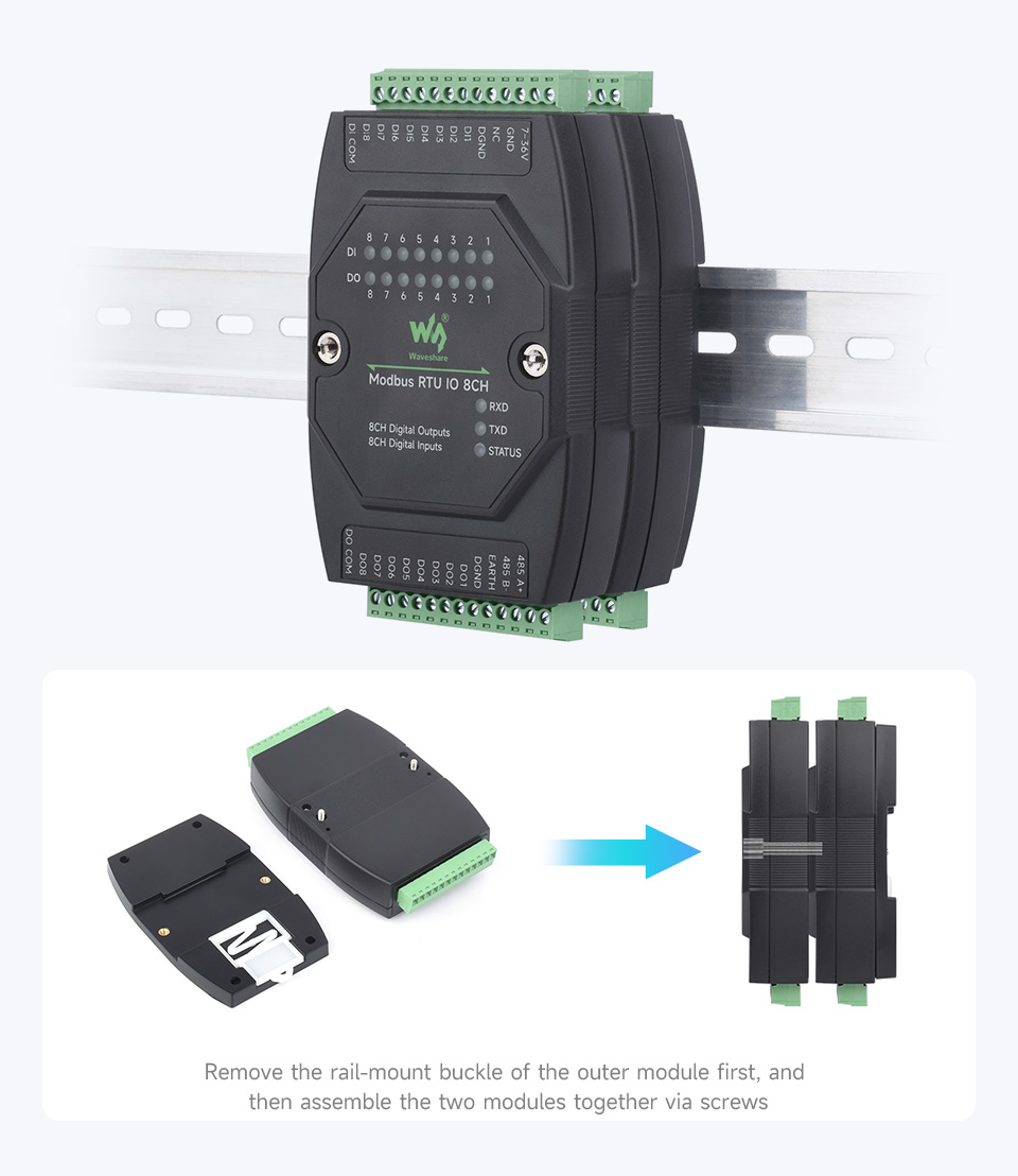
- Rail-Mount Design: Features a rail-mount case design for easy installation on a 35mm standard guide rail and supports stacking combinations for modular setups.
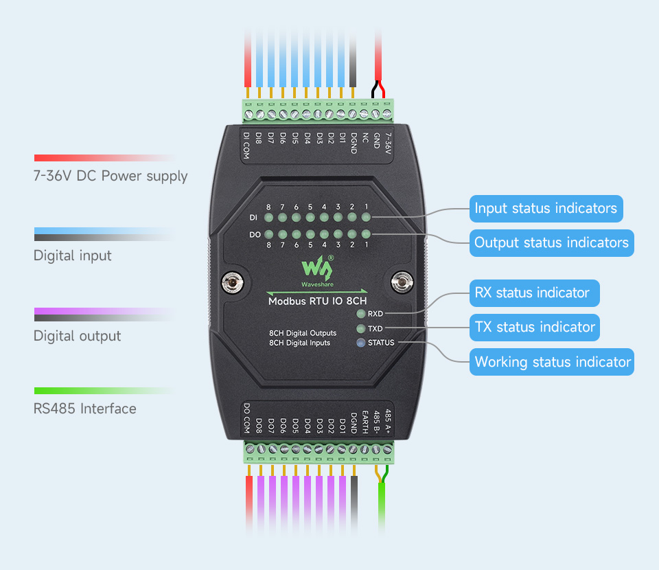
- Status Indicators: Multiple LEDs indicate input and output status, MCU status, and signal transceiving status (RXD, TXD, STATUS).
4. Specifications
| Parameter | Value |
|---|---|
| Communication Interface | RS485 |
| Baud Rate | 4800, 9600, 19200, 38400, 57600, 115200, 128000, 256000 |
| Default Communication Format | 9600, N, 8, 1 |
| Modbus Protocol | Standard Modbus RTU protocol |
| Power Supply | DC 7~36V |
| Digital Input (DI) | 8 channels, 5~36V, passive / active input (NPN or PNP), bi-directional optocoupler isolation |
| Digital Output (DO) | 8 channels, 5~36V, open-drain output, output load: 500mA per channel (MAX) |
5. Setup
5.1. Physical Installation
The module is designed for rail-mount installation. It supports a 35mm standard guide rail. To install, simply clip the module onto the rail using its integrated buckle. For stacking multiple modules, remove the rail-mount buckle of the outer module first, then assemble the two modules together via screws.
5.2. Wiring
Ensure all power is disconnected before performing any wiring. Refer to the diagrams below for correct connections.
5.2.1. Power Supply and RS485 Interface
Connect a DC power supply within the 7~36V range to the designated power terminals. Connect the RS485 interface to your host computer or control system.
5.2.2. Digital Input (DI) and Digital Output (DO) Wiring
The module supports both active (wet contact) and passive (dry contact) digital inputs. Digital outputs are open-drain type. Refer to the detailed connection diagrams for proper wiring of sensors, switches, and loads.
5.3. Interface and LED Indicators
The module features various terminals and LED indicators to monitor its status and operation:
- Input Status Indicators (DI): LEDs for each digital input channel (DI0-DI7) show the current state of the input.
- Output Status Indicators (DO): LEDs for each digital output channel (DO0-DO7) show the current state of the output.
- RX Status Indicator: Lights up when data is being received via RS485.
- TX Status Indicator: Lights up when data is being transmitted via RS485.
- STATUS Indicator: Indicates the overall working status of the module.
6. Operating Modes
The module supports multiple output control modes, with each channel configurable independently:
6.1. Normal Mode (Command Direct Control)
In this mode, the digital outputs are directly controlled by sending Modbus RTU commands from a host computer. This allows for immediate ON/OFF control of connected loads.
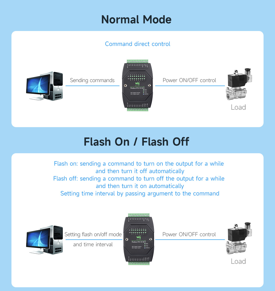
6.2. Flash On / Flash Off Mode
This mode allows for timed control of the outputs. By sending a command with a specific argument, an output can be turned ON for a set duration and then automatically turn OFF (Flash On), or turned OFF for a set duration and then automatically turn ON (Flash Off). This is useful for applications requiring momentary actions.

6.3. DI/DO Linkage Control
In this mode, the status of a digital output channel directly follows the status of a corresponding digital input channel. When the input changes state, the linked output will mirror that change.
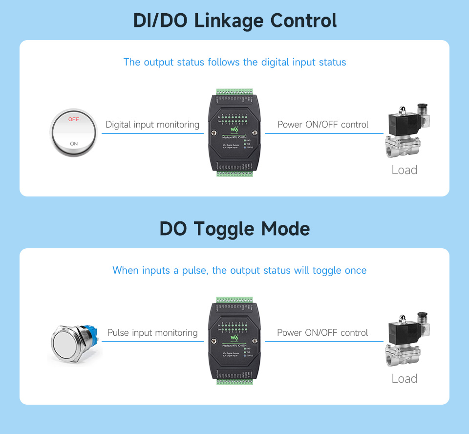
6.4. DO Toggle Mode
When a pulse is detected on a configured input, the corresponding digital output will toggle its state (e.g., if it was OFF, it turns ON; if it was ON, it turns OFF). This is useful for applications like push-button control.

7. Maintenance
- Cleaning: Keep the module clean and free from dust and debris. Use a soft, dry cloth for cleaning. Avoid using liquids or abrasive cleaners.
- Environmental Conditions: Ensure the module operates within its specified temperature and humidity ranges. Avoid exposure to extreme temperatures, direct sunlight, or high moisture.
- Connection Checks: Periodically inspect all wiring connections to ensure they are secure and free from corrosion. Loose connections can lead to intermittent operation or damage.
- Firmware Updates: Check the Waveshare website for any available firmware updates that may improve performance or add new features. Follow the provided instructions carefully for any update procedures.
8. Troubleshooting
- No Power/Module Not Responding:
- Verify that the DC 7~36V power supply is correctly connected and providing the correct voltage.
- Check the power supply terminal adapter for proper connection.
- Ensure the power source is active.
- RS485 Communication Issues:
- Check RS485 A+ and B- connections for correct polarity.
- Ensure the baud rate and communication format (e.g., 9600, N, 8, 1) match between the module and the host device.
- Verify the device address is correctly configured and unique on the bus.
- Check for proper termination resistors on the RS485 bus if applicable.
- Observe the RXD and TXD LEDs for activity to confirm data transmission/reception.
- Digital Input Not Registering:
- Confirm the input device (sensor, switch) is correctly wired as either passive (dry contact) or active (wet contact) according to the diagrams.
- Check the voltage level of the input signal (must be 5~36V).
- Ensure the input device is functioning correctly.
- Observe the corresponding DI LED on the module.
- Digital Output Not Activating:
- Verify the Modbus command sent to activate the output is correct.
- Check the load connected to the digital output; ensure it is within the 500mA maximum sinking current.
- Ensure the load's power supply is connected and functional.
- Observe the corresponding DO LED on the module.
9. User Tips
No specific user tips were available from provided reviews or Q&A content. For optimal performance, always ensure stable power supply and correct wiring according to the diagrams. When cascading multiple modules, verify each module has a unique Modbus address.
10. Warranty & Support
For warranty information, technical support, or further assistance, please refer to the official Waveshare website or contact your point of purchase. Keep your purchase receipt for warranty claims.


