
1. Introduction
This manual provides essential information for the safe and efficient operation of your AISET NTTF-2000 Series Hot Stamping Machine Controller. This device is designed for precise temperature and time control in industrial applications, particularly hot stamping processes. Please read this manual thoroughly before installation and operation.
2. Safety Information
- Electrical Safety: Ensure all wiring is performed by qualified personnel in accordance with local electrical codes. Disconnect power before making any connections or performing maintenance.
- Voltage: Verify that the power supply voltage matches the controller's specifications (85-264VAC, 50Hz).
- Environment: Install the controller in a clean, dry environment, away from excessive heat, moisture, corrosive gases, or strong vibrations.
- Grounding: Proper grounding is essential to prevent electrical shock and ensure stable operation.
- Emergency Stop: Always have an accessible emergency stop mechanism for the hot stamping machine.
3. Package Contents
Upon opening the package, please verify that all items are present and undamaged:
- 1x AISET NTTF-2000 Series Hot Stamping Machine Controller
- 1x User Manual (this document)
4. Specifications
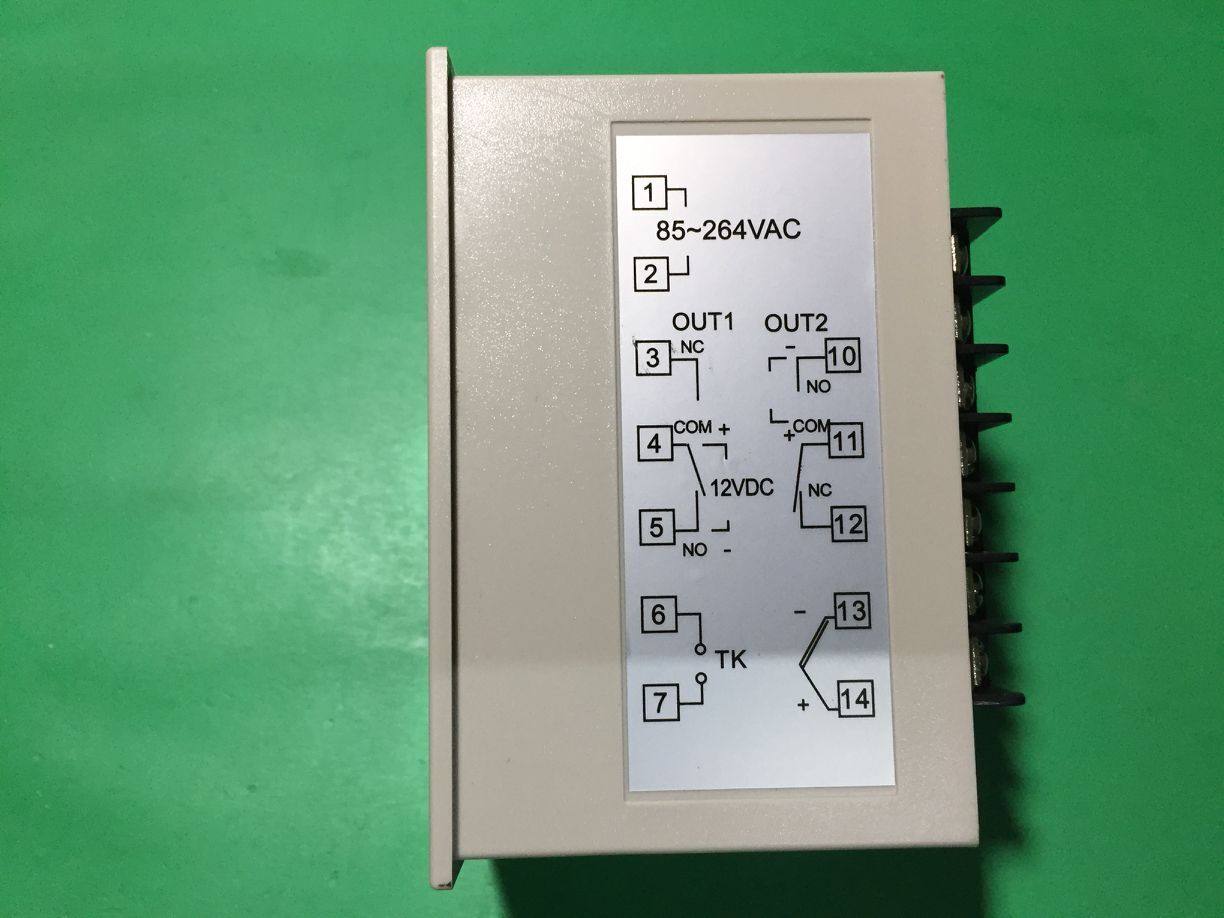
| Feature | Specification |
|---|---|
| Model Number | NTTF-2000 Series (e.g., NTTF-2421V, NTTF-2411V, NTTF-2411WR-G, NTTF-2412V) |
| Function | Temperature and Time Controller |
| Power (W) | 2 W |
| Voltage | 85-264VAC / 50Hz |
| Temperature Range | 0-400°C (K-type thermocouple input) |
| Accuracy | 0.5 Level |
| Smart Device | No |
| Origin | Mainland China |
| Package Dimensions (L x W x H) | 20 cm x 10 cm x 15 cm |
| Package Weight | 0.5 kg |
5. Setup
5.1 Mounting
The controller is designed for panel mounting. Ensure adequate space for ventilation and access to wiring terminals. Cut a rectangular opening in your control panel according to the controller's dimensions and secure it using the provided mounting clips (if applicable).
5.2 Wiring Diagram
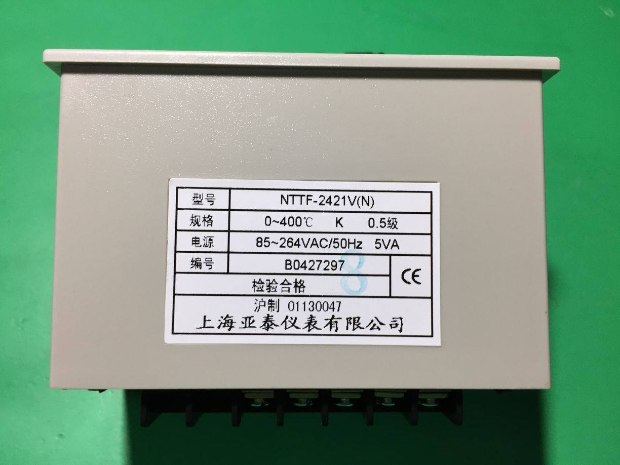
Refer to the wiring diagram on the side of the controller and the detailed illustration below for correct connections. Improper wiring can damage the device or cause safety hazards.

Terminal Connections:
- Terminals 1 & 2: Power Input (85-264VAC)
- Terminals 3, 4, 5: Output 1 (OUT1) - Relay contacts (3: NC, 4: COM+, 5: NO)
- Terminals 6 & 7: Thermocouple Input (TK) - Connect K-type thermocouple (6: -, 7: +)
- Terminals 10, 11, 12: Output 2 (OUT2) - Relay contacts (10: NO, 11: COM+, 12: NC)
- Terminals 13 & 14: 12VDC Output (13: -, 14: +)
Ensure all connections are secure and insulated. Double-check wiring before applying power.
6. Operating Instructions
6.1 Front Panel Overview

The front panel features two digital displays (Temperature and Time), control buttons, and indicator lights:
- Temperature Display: Shows current temperature and set temperature.
- Time Display: Shows current time and set time.
- SETTEM Button: Used to enter temperature setting mode.
- SETTIME Button: Used to enter time setting mode.
- SET Button: Used to confirm settings.
- Up/Down Arrow Buttons: Used to adjust values.
- OUT Indicator: Illuminates when the output relay is active.
- AT/ALM Indicator: Illuminates for auto-tuning or alarm conditions.
6.2 Basic Operation
- Power On: After proper wiring, apply power to the controller. The displays will light up, typically showing a self-test sequence or current readings.
- Setting Temperature:
- Press the SETTEM button. The temperature display will flash, indicating it's in setting mode.
- Use the Up and Down arrow buttons to adjust the desired temperature setpoint.
- Press the SET button to confirm and save the setting.
- Setting Time:
- Press the SETTIME button. The time display will flash.
- Use the Up and Down arrow buttons to adjust the desired time setpoint (in seconds).
- Press the SET button to confirm and save the setting.
- Monitoring: The controller will continuously monitor the temperature and time, activating the output relays as programmed to maintain the set conditions.
6.3 Advanced Settings (PID Tuning, Alarms)
For advanced settings such as PID auto-tuning, alarm configurations, or specific operational modes, please refer to the comprehensive technical manual or contact AISET technical support. These settings typically involve specific button combinations or menu navigation not covered in this basic operational guide.
7. Maintenance
- Cleaning: Regularly wipe the front panel with a soft, dry cloth. Do not use abrasive cleaners or solvents.
- Connection Check: Periodically inspect all wiring connections for tightness and signs of corrosion or damage.
- Ventilation: Ensure that the controller's ventilation openings are not obstructed to prevent overheating.
- Sensor Inspection: Check the thermocouple for physical damage or wear. Replace if necessary to ensure accurate temperature readings.
8. Troubleshooting
| Problem | Possible Cause | Solution |
|---|---|---|
| Controller does not power on | No power supply; incorrect wiring | Check power connections (Terminals 1 & 2) and ensure power is supplied. Verify wiring against diagram. |
| Temperature reading is inaccurate or 'HHHH'/'LLLL' displayed | Thermocouple faulty or incorrectly connected | Check thermocouple wiring (Terminals 6 & 7) for correct polarity and secure connection. Inspect thermocouple for damage and replace if necessary. |
| Output not activating | Incorrect setpoint; wiring error; controller in manual mode or alarm state | Verify temperature/time setpoints. Check output wiring (Terminals 3-5 or 10-12). Check AT/ALM indicator for alarm conditions. |
| Settings cannot be changed | Keypad lock engaged; parameter access restricted | Refer to the full technical manual for information on keypad lock or parameter access. |
9. User Tips
- For optimal temperature stability, consider performing an auto-tune (AT) function after initial setup or if the heating element or load changes significantly. Consult the full technical manual for auto-tuning procedures.
- Always ensure the K-type thermocouple is correctly installed and making good contact with the measurement point for accurate readings.
- When setting time, remember the unit is typically in seconds. Plan your hot stamping cycle accordingly.
10. Warranty and Support
For warranty information, technical support, or service inquiries, please contact your original point of purchase or the manufacturer directly. Keep your purchase receipt and product model number handy when contacting support.