
1. Introduction
The Hantek DSO2D15 is a versatile 2-channel digital storage oscilloscope designed for electronics repair, development, and educational purposes. It features a 150MHz analog channel bandwidth, 1GSa/s real-time sample rate, and an 8M memory depth, providing detailed waveform analysis. This manual provides essential information for setting up, operating, maintaining, and troubleshooting your oscilloscope.

2. Package Contents
Please check the contents of your package upon arrival. If any items are missing or damaged, contact your vendor immediately.

- Hantek DSO2D15 Digital Storage Oscilloscope
- USB Cable
- Power Cord
- 2 Oscilloscope Probes
- User Manual (this document)
- Certification Card
3. Setup
3.1 Front Panel Overview
Familiarize yourself with the controls and connectors on the front panel of your oscilloscope:

- Retractable Handle: For portability.
- Options Buttons (F1-F6): Context-sensitive function buttons.
- Common Function Area: Buttons for Menu, Measure, Acquire, Utility, Cursor, Display, Save/Recall, Default Setup, Help.
- Executive Control: Knobs and buttons for general settings and navigation.
- USB Port: For data transfer and saving screenshots.
- Analog Signal Input Channels (CH1, CH2): BNC connectors for probe input.
- External Trigger Input Channel (EXT TRIG/GEN OUT): For external trigger signals or waveform generator output.
- Probe Original: Probe compensation test point.
- Trigger Control: Adjusts trigger level and mode.
- Power Switch: Turns the device on/off.
3.2 Power Connection
- Connect the provided power cord to the power input on the rear panel of the oscilloscope.
- Plug the other end of the power cord into a suitable AC power outlet.
3.3 Probe Connection
- Connect the oscilloscope probes to the CH1 and/or CH2 BNC input connectors on the front panel.
- Ensure the probe's ground clip is securely connected to the circuit's ground.
4. Operating Instructions
4.1 Power On/Off
Press the Power Switch on the front panel to turn the oscilloscope on or off.
4.2 Basic Waveform Display
- Connect a signal source to CH1 or CH2 using a probe.
- Press the AUTO SCALE button (often labeled F4 or similar in the common function area) for automatic waveform adjustment.
- Adjust the VERTICAL (Volts/Div) and HORIZONTAL (Time/Div) knobs to fine-tune the waveform display.
4.3 Waveform Generator (DSO2D10, DSO2D15 only)
The DSO2D15 model includes a built-in 1-channel 5MHz waveform generator. This function supports arbitrary waveform burst output and modulation waveform output.

4.4 Automatic Measurements
The oscilloscope supports 32 types of automatic measurements with real-time statistics (maximum, minimum, standard deviation, etc.).

4.5 Digital Voltmeter (DVM) and Frequency Indicator
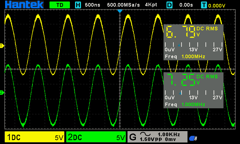
The device includes a 5-bit digital voltmeter and a 6-bit hardware frequency indicator function. You can enable DVM for specific channels to display DC RMS, AC RMS, or DC voltage and frequency.
4.6 Serial Bus Trigger and Decode
The oscilloscope supports serial bus triggering and decoding for protocols such as RS232/UART, I2C, SPI, CAN, and LIN, including a protocol monitoring function.

4.7 Memory Depth
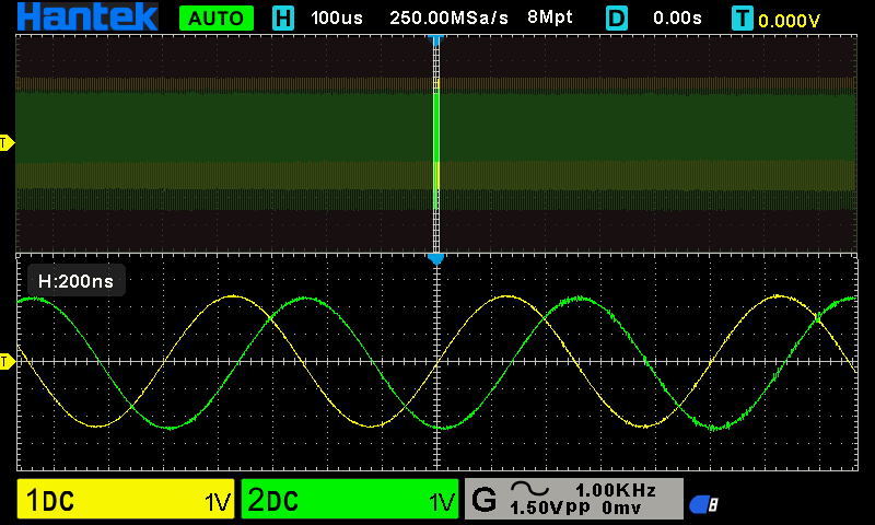
With an 8M memory depth, the oscilloscope can capture and display waveforms with high detail, reducing distortion and restoring real waveforms accurately.
4.8 PASS/FAIL Testing
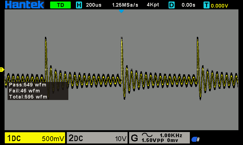
The PASS/FAIL function allows you to set thresholds and automatically determine if a waveform meets specified criteria.
4.9 Mathematical Operations and FFT
Perform various mathematical operations on waveforms and utilize the Fast Fourier Transform (FFT) for frequency domain analysis.

4.10 X-Y Format
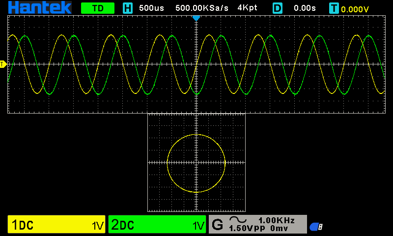
Display waveforms in X-Y format, useful for phase relationship analysis, and view in dual windows.
4.11 Saving and Recalling Data
The oscilloscope allows saving various data formats, including settings, waveforms, reference waveforms, CSV data, and screenshots. Use the SAVE/RECALL menu to manage your data.
The USB port enables one-click screenshot functionality for quick documentation.
5. Maintenance
5.1 Cleaning
To clean the oscilloscope, use a soft, damp cloth. Do not use abrasive cleaners or solvents, as they may damage the casing or screen. Ensure the device is powered off and unplugged before cleaning.
5.2 Storage
Store the oscilloscope in a dry, dust-free environment away from direct sunlight and extreme temperatures. When not in use, it is recommended to cover the device to prevent dust accumulation.
6. Troubleshooting
- No waveform displayed: Check probe connections, ensure the signal source is active, and verify channel settings (e.g., input coupling, vertical scale). Try pressing the AUTO SCALE button.
- Unstable waveform: Adjust the trigger level and trigger mode. Ensure the trigger source is correctly selected.
- Incorrect measurements: Verify probe attenuation settings (1X, 10X) on both the probe and the oscilloscope. Ensure proper grounding.
- Device unresponsive: Power cycle the oscilloscope. If the issue persists, contact support.
7. Specifications
Below are the key specifications for the Hantek DSO2D15 model:
| Feature | Specification (DSO2D15) |
|---|---|
| Channels | 2CH + 1CH (Waveform Generator) |
| Bandwidth | 150MHz |
| Real Time Sampling Rate | 1GSa/S |
| Memory Depth | 8M |
| Built-in Signal Source | 1CH (5MHz Waveform Generator) |
| Rise Time at BNC (typical) | 2.3NS |
| Vertical Range | 2mV/div ~ 10V/div |
| Vertical Resolution | 8bit |
| Max Waveform Capture Rate | 30,000wfm/s |
| Display Type | 7" TFT LCD display diagonally |
| Display Resolution | 800*480 Pixels |
| Trigger Types | Edge, Pulse width, Video, Slope, Overtime, Window, Pattern, Interval, Delay, UART, LIN, CAN, SPI, IIC |
| Decode & Protocol Analysis | RS232/UART, I2C, SPI, CAN, LIN |
| Auto Measurements | 32 kinds with statistics |
| Digital Voltmeter (DVM) | 2 sets, 5-bit |
| Hardware Frequency Indicator | 6-bit |
| External Interface | USB Host/Device |
| Oscilloscope Size | 318mm x 140mm x 150mm |
| Certification | CE |
| Origin | Mainland China |
Note: DSO2C10 and DSO2C15 models do not include the waveform generator function.
8. User Tips
- While the FFT function is generally good for an entry-level oscilloscope, advanced users might find it less robust compared to higher-end models. Adjusting settings and experimenting with different windows can optimize results.
- If you are looking for a hardware frequency counter, explore the DVM (Digital Voltmeter) function within the measurement menu. It provides frequency readings alongside voltage measurements.
- Utilize the save functionality to store frequently used setups or important waveform captures. This can significantly speed up recurring tests and aid in documentation.
9. Warranty and Support
For warranty information, technical support, or service inquiries, please refer to the contact information provided by your original vendor or the manufacturer's official website. Keep your purchase receipt as proof of purchase for warranty claims.