
1. Introduction
This manual provides comprehensive instructions for the installation, operation, maintenance, and troubleshooting of the AISET YLE series constant temperature controllers. These devices are designed for precise temperature control in various industrial and laboratory applications. Please read this manual thoroughly before operating the device to ensure safe and efficient use.
2. Safety Precautions
- Always disconnect power before performing any wiring or maintenance.
- Ensure the power supply voltage matches the specifications of the controller.
- Do not operate the device in environments exceeding the maximum ambient temperature (50°C).
- Avoid exposing the controller to moisture, dust, or corrosive gases.
- Only qualified personnel should perform installation and wiring.
- Ensure proper grounding to prevent electrical shock.
3. Product Overview
3.1 Front Panel Layout
The front panel features dual 4-digit LED displays for Process Value (PV) and Set Value (SV), along with various indicator lights and control buttons.


3.2 Rear/Internal Terminals
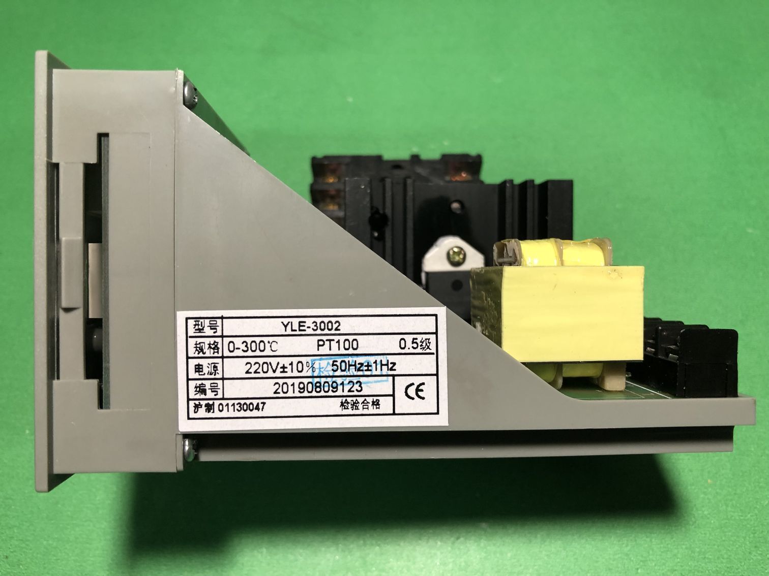
The rear of the controller houses the wiring terminals for power input, sensor input, and control output. Refer to the internal views for terminal identification.

4. Setup and Installation
4.1 Mounting
The AISET YLE series controllers are designed for panel mounting. Ensure adequate space for ventilation and access to wiring terminals. Secure the controller firmly into the panel cutout using the provided mounting brackets.
4.2 Wiring
Refer to the internal diagrams (Figures 4, 5, 6) for precise terminal identification. All wiring should be done with the power disconnected.
- Power Input: Connect the main power supply (220V AC, 50Hz) to the terminals labeled 'L' (Live) and 'N' (Neutral) under the 'INPUT' section.
- Sensor Input: Connect your PT100 temperature sensor to the designated sensor input terminals. Ensure correct polarity if applicable, though PT100 sensors are typically non-polarized for resistance measurement.
- Control Output: Connect your heating or cooling device to the 'OUT' terminals. The controller will switch this output based on your set temperature. Ensure the load current does not exceed the controller's relay rating.
- Grounding: Connect the ground wire to the designated ground terminal for safety.
Warning: Incorrect wiring can damage the device and pose a safety hazard. If unsure, consult a qualified electrician.
5. Operation
5.1 Power On
Once wired correctly, apply power to the controller. The PV display will show the current temperature measured by the sensor, and the SV display will show the set temperature.
5.2 Setting the Temperature (SV)
- Press the SET button. The SV display will start flashing, indicating it's in setting mode.
- Use the Up (▲) and Down (▼) arrow buttons to adjust the desired temperature value.
- Press SET again to confirm the new value and exit setting mode. The controller will now regulate the temperature to the new SV.
5.3 Indicator Lights
- RUN: Indicates the controller is operating normally.
- OUT: Illuminates when the control output is active (e.g., heating element is on).
- ALM: Illuminates when an alarm condition is met (e.g., temperature exceeds limits).
- COOL/COL: (Depending on model) Indicates cooling output is active.
6. Maintenance
- Cleaning: Wipe the front panel with a soft, dry cloth. Do not use abrasive cleaners or solvents.
- Environment: Ensure the operating environment remains within specified temperature and humidity ranges.
- Connections: Periodically check all wiring connections to ensure they are secure and free from corrosion.
- Storage: If storing the device, keep it in a dry, dust-free environment at room temperature.
7. Troubleshooting
| Problem | Possible Cause | Solution |
|---|---|---|
| No power/Display off | No power supply; Incorrect wiring; Blown fuse | Check power connections; Verify wiring; Replace fuse if necessary (by qualified personnel). |
| Incorrect temperature reading (PV) | Sensor faulty; Sensor incorrectly wired; Sensor type mismatch | Check sensor for damage; Verify sensor wiring; Ensure PT100 sensor is used. |
| Output (OUT) not switching | Set value (SV) too close to PV; Output device faulty; Wiring issue | Adjust SV to create a clear difference; Test output device independently; Check output wiring. |
| Temperature overshoots/undershoots | PID parameters not tuned; Hysteresis setting incorrect | Refer to advanced settings for PID tuning (if available); Adjust hysteresis (deadband) if using ON/OFF control. |
8. Specifications
| Feature | Details |
|---|---|
| Brand | AISET |
| Model Numbers | YLE-3000, YLE-3001, YLE-3002, YLE-3005, YLE-3006, YLE-6000, YLE-6412V-2S |
| Material | ABS |
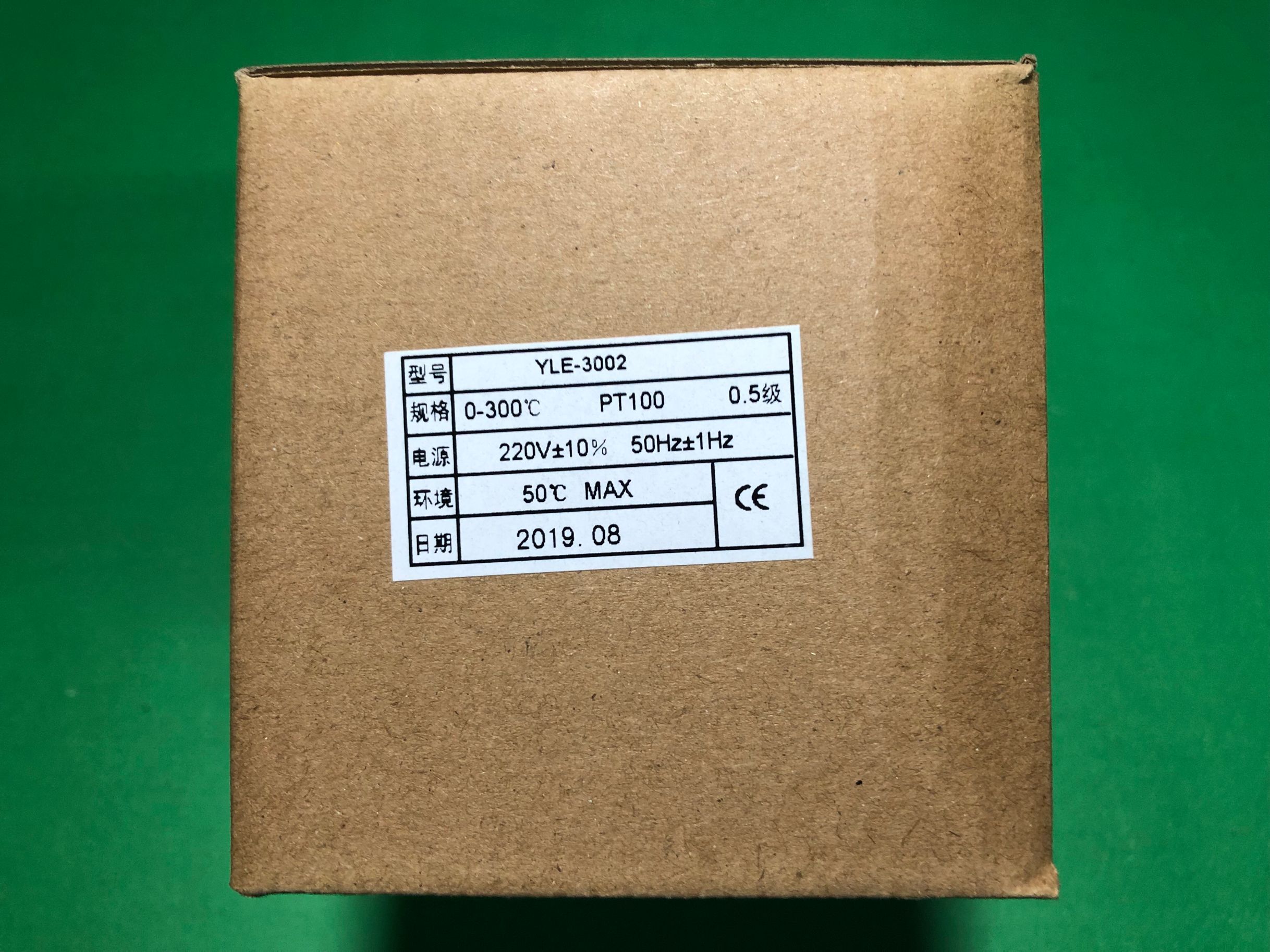
| Temperature Range (YLE-3002) | 0-300°C |
| Temperature Range (YLE-6412V-2S) | 0-400°C |
| Sensor Type | PT100 |
| Accuracy | Class 0.5 |
| Power Supply | 220V±10% 50Hz±1Hz |
| Max Environment Temperature | 50°C |
| Package Dimensions (Approx.) | 20 cm (Length) x 15 cm (Width) x 10 cm (Height) |
| Package Weight (Approx.) | 0.6 kg |
| Origin | Mainland China |
Note: Specific features and parameters may vary slightly between different models within the YLE series. Always refer to the label on your specific unit for exact specifications.


9. User Tips
- For critical applications, always use a secondary temperature monitoring device to verify readings.
- Consider the thermal mass of your system when setting control parameters to avoid excessive overshoot or undershoot.
- Ensure the temperature sensor is placed in a representative location for accurate measurement.
- If the controller is used in a dusty environment, regular cleaning of the ventilation openings is recommended to prevent overheating.
10. Warranty and Support
For warranty information, technical support, or service inquiries, please contact your original point of purchase or the manufacturer directly. Keep your purchase receipt as proof of purchase.