
1. Introduction
This manual provides essential information for the safe and effective use of the AISET NTTE-2401V-1 and YLE-2001 temperature controllers. These devices are designed for precise temperature control in various industrial applications, including heat press machines, with a maximum temperature range of 400℃ using a K-type thermocouple. Please read this manual thoroughly before installation and operation.

Figure 1: Front Panel of AISET YLE-2001 Temperature Controller
2. Specifications
The following table outlines the key specifications for the AISET NTTE-2401V-1 / YLE-2001 temperature controller:
| Feature | Specification |
|---|---|
| Model Numbers | NTTE-2401V-1, YLE-2001 |
| Material | ABS |
| Temperature Range | 0-400℃ (K-type thermocouple) |
| Accuracy | 0.5 level |
| Power Supply | 220V ±10% 50Hz ±1Hz |
| Operating Environment | Max 50℃ |
| Package Dimensions (L x W x H) | 20 cm x 15 cm x 10 cm |
| Package Weight | 0.6 kg |
| Origin | Mainland China |
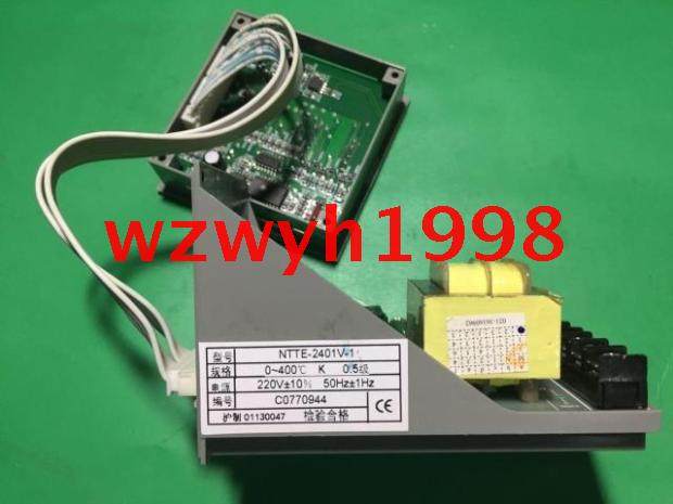
Figure 2: Internal view with specification label for NTTE-2401V-1
3. Installation and Wiring
Proper installation and wiring are crucial for the safe and accurate operation of the temperature controller. Ensure all power is disconnected before proceeding with any wiring.
3.1 Mounting
The controller is designed for panel mounting. Cut an appropriate opening in your control panel and secure the unit using the provided mounting brackets.
3.2 Wiring Connections
Refer to the wiring diagram below for connecting power, sensor input, and control outputs. While the diagram shown is for a similar AISET model (ND-8811), the general terminal functions are typically consistent across similar controllers. Always verify connections with your specific unit's markings.

Figure 3: Reference Wiring Diagram (ND-8811 model)
Terminal Descriptions (Refer to Figure 3):
- Power Supply (AC 85-264V): Connect your main power supply to terminals 1 and 2.
- Sensor Input (PV): Connect your K-type thermocouple to terminals 17 and 18. Ensure correct polarity.
- Control Output 1 (OUT1): Connect your primary heating/cooling element to terminals 7 (NO - Normally Open) and 8 (NC - Normally Closed).
- Control Output 2 (OUT2): Connect a secondary heating/cooling element or alarm to terminals 9 (NO) and 10 (NC).
- Alarm Output 1 (ALM1): Connect an external alarm device to terminals 11 (NO) and 12 (NC).

Figure 4: Terminal Block Detail
4. Operation
The AISET YLE-2001 features a clear dual-display and intuitive button interface for easy operation.
4.1 Front Panel Overview
- PV Display (Upper): Shows the current Process Value (actual temperature).
- SV Display (Lower): Shows the Set Value (target temperature).
- SET Button: Used to enter parameter setting mode and confirm selections.
- AT Button: Initiates or cancels the Auto-Tuning function.
- Up Arrow (TIME) Button: Used to increase values or navigate menus.
- Down Arrow Button: Used to decrease values or navigate menus.
- AT Indicator: Lights up when auto-tuning is active.
- OUT1 Indicator: Lights up when Output 1 is active.
- OUT2 Indicator: Lights up when Output 2 is active.
4.2 Setting the Target Temperature (SV)
- Press the SET button once. The SV display will start flashing.
- Use the Up Arrow (TIME) or Down Arrow buttons to adjust the target temperature to your desired value.
- Press the SET button again to confirm the new SV and exit the setting mode.
4.3 Auto-Tuning (AT)
Auto-tuning helps the controller optimize its PID parameters for stable and accurate temperature control. It is recommended to perform auto-tuning when the controller is first installed or if the controlled system characteristics change significantly.
- Ensure the system is at a stable temperature, preferably near the desired SV.
- Press and hold the AT button for a few seconds until the AT indicator lights up. The controller will begin the auto-tuning process.
- During auto-tuning, the temperature may fluctuate around the SV. Do not interrupt the process.
- Once auto-tuning is complete, the AT indicator will turn off, and the controller will operate with the optimized PID parameters.
5. Maintenance
To ensure the longevity and reliable performance of your AISET temperature controller, follow these maintenance guidelines:
- Cleaning: Regularly wipe the front panel with a soft, dry cloth. Avoid using abrasive cleaners or solvents that could damage the display or casing.
- Inspection: Periodically check all wiring connections for tightness and signs of wear or corrosion. Ensure the sensor is securely in place and free from damage.
- Environment: Operate the controller within its specified environmental limits (Max 50℃). Avoid exposure to excessive dust, moisture, or corrosive gases.
6. Troubleshooting
If you encounter issues with your temperature controller, refer to the following common problems and solutions:
| Problem | Possible Cause | Solution |
|---|---|---|
| Controller does not power on | No power supply; incorrect wiring | Check power connections (terminals 1 & 2); ensure power source is active. |
| PV display shows 'HHHH' or 'LLLL' | Sensor open circuit or short circuit; incorrect sensor type | Check thermocouple wiring (terminals 17 & 18); ensure K-type thermocouple is used and functioning. |
| Temperature not reaching SV | Heating element issue; incorrect output wiring; poor PID tuning | Verify heating element operation; check OUT1 wiring; perform auto-tuning. |
| Temperature overshoots/undershoots SV | Poor PID tuning | Perform auto-tuning to optimize PID parameters. |
| Output indicator (OUT1/OUT2) not lighting up | Controller not calling for output; output wiring issue | Check SV and PV values; verify output wiring to load. |
If the problem persists after attempting these solutions, please contact customer support.
7. User Tips
- For best performance, ensure the temperature sensor is placed accurately to reflect the temperature of the controlled process.
- Always perform auto-tuning after significant changes to the system (e.g., changing heating elements, modifying the process volume) to maintain optimal control.
- Keep the controller's ventilation clear to prevent overheating, especially in enclosed control panels.
8. Warranty and Support
For any technical assistance, warranty claims, or further inquiries regarding your AISET NTTE-2401V-1 / YLE-2001 temperature controller, please contact the seller or manufacturer directly. Keep your purchase records handy when seeking support.