
1. Product Overview
The Sumry MPS-VIII ECO Series Hybrid Solar Inverter is a versatile power solution designed for both on-grid and off-grid solar systems. It features a pure sine wave output, ensuring clean and stable power for sensitive electronics. Available in 4.2kW (24V) and 6.2kW (48V) models, it integrates an advanced 120A MPPT solar charge controller and offers dual output capabilities.

Key Features:
- Pure sine wave output for sensitive electronics.
- Output power factor of 1.0.
- Optional WiFi & GPRS connectivity for iOS and Android monitoring.
- Capable of running without a battery.
- One-key restoration to factory settings.
- Built-in Lithium battery automatic activation.
- Dual communication ports for battery and WiFi communication.
- Integrated 120A MPPT solar charge controller.
- High PV input voltage range: 60-500VDC.
- Built-in anti-dust kit for enhanced durability in harsh environments.
- Smart battery charge design to optimize battery life.
- Dual output functionality.
2. Safety Information
This inverter is designed with multiple protection features to ensure safe operation for both the unit and connected devices. Always adhere to local electrical codes and safety guidelines during installation and operation.
Integrated Protections:
- Overload Protection
- Short Circuit Protection
- Battery Protection
- Overheating Protection
- Overcurrent Protection
- High/Low Voltage Protection

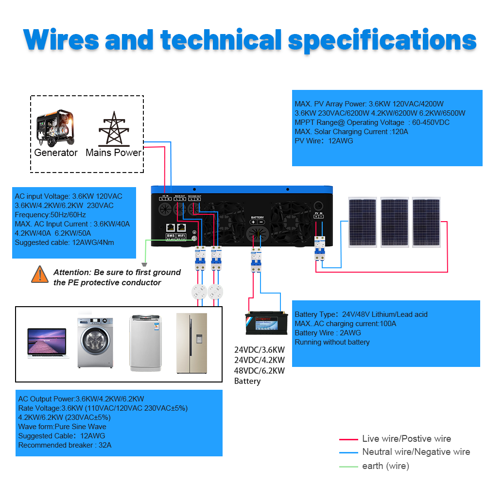
Important: Ensure the PE (Protective Earth) conductor is properly grounded during installation to prevent electrical hazards.
3. Product Components and Ports
Familiarize yourself with the inverter's layout and connection points before installation.

Intelligent Cooling System:
The solar inverter incorporates a built-in sensor chip that intelligently adjusts the fan rotation speed based on ambient temperature and the quality of the air, ensuring optimal performance and longevity.

4. Specifications
Detailed technical specifications for the Sumry MPS-VIII ECO Series Hybrid Solar Inverter.

Key Technical Parameters:
- MPPT Solar Charging: 120A
- High PV Input Voltage Range: 60-500VDC
- AC Output Voltage: 220-240VAC
- Max Solar Charge Power: 6200W (for 3.6kW/4.2kW models), 6500W (for 6.2kW model)
- Frequency: 50/60Hz
- Battery Voltage: 24V (for 3.6kW/4.2kW models), 48V (for 6.2kW model)
- Operation: Can run without battery.
Detailed Specifications Table:
| Feature | VICTOR NM-ECO-3.6KW PLUS | VICTOR NM-ECO-4.2KW PLUS | VICTOR NM-ECO-6.2KW PLUS |
|---|---|---|---|
| Phase | 1-Phase | ||
| Max. PV Array Power | 6200W | 4200W | 6500W |
| Max. Solar Charging Current | 120A | ||
| MPPT Range @ Operating Voltage | 60-450VDC | ||
| Max. PV Input Voltage | 500VDC | ||
| GRID-TIE OPERATION | |||
| Nominal Output Voltage | 220/230/240VAC | ||
| Output Voltage Range | 195-253VAC | ||
| Nominal Output Current | 15.7A | 18.2A | 27.0A |
| Power Factor | >0.99 | ||
| Max. Conversion Efficiency (DC/AC) | 98% | ||
| TWO LOAD OUTPUT POWER | |||
| Full Load | 3600W | 4200W | 6200W |
| Max Main Load | 3600W | 4200W | 6200W |
| Maximum Second Load (battery mode) | 1200W | 1400W | 2067W |
| Maximum Load Off Voltage | 26VDC | 52VDC | 52VDC |
| Maximum Load Return Voltage | 27VDC | 52VDC | 52VDC |
| OFF-GRID OPERATION | |||
| AC Start-up Voltage/Auto Restart Voltage | 120-140VAC/180VAC | ||
| Acceptable Input Voltage Range | 90-280VAC or 170-280VAC | ||
| Frequency Range | 50/60Hz | ||
| Maximum AC Input Current | 21.1A | 24.7A | 36.4A |
| PV INPUT (DC) | |||
| Nominal DC Voltage/Maximum DC Voltage | 360/500VDC | ||
| MPPT Voltage Range | 60-450VDC | ||
| Maximum Input Current | 1/18A | 1/22A | 1/22A |
| BATTERY MODE OUTPUT (AC) | |||
| Nominal Output Voltage | 220/230/240VAC | ||
| Output Wave Form | Pure sine wave | ||
| Efficiency (Peak) | 94% | ||
| BATTERY CHARGER | |||
| Nominal DC Voltage | 24VDC | 24VDC | 48VDC |
| Maximum AC Charging Current | 100A | 100A | 100A |
| Maximum Solar+AC Charging Current | 120A | 120A | 120A |
| GENERAL | |||
| Physical Dimension (H*W*D)mm | 420*350*110 | 500*415*180 | |
| Net Weight (kg) | 8.0 | 8.9 | 10.3 |
| Gross Weight (kg) | 9.0 | 10.0 | 11.0 |
| INTERFACE | |||
| Communication Port | RS232/RS485/WIFI/GPRS/LITHIUM BATTERY | ||
| ENVIRONMENT | |||
| Humidity | 5% to 95% Relative Humidity (Non-condensing) | ||
| Operating Temperature | -10°C to 50°C | ||
| STANDARD | |||
| Compliance Safety | CE | ||
5. Setup & Installation
Proper installation is crucial for the safe and efficient operation of your hybrid solar inverter. Follow these steps carefully.
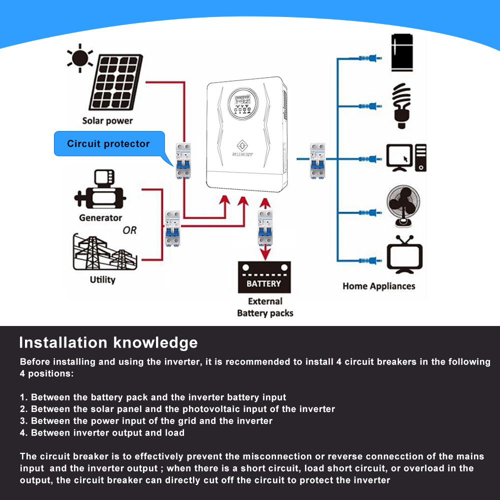
5.1 System Architecture Overview

5.2 Wiring and Circuit Breaker Installation
Before installing and using the inverter, it is recommended to install circuit breakers in the following positions to ensure safety and prevent damage:
- Between the battery pack and the inverter battery input.
- Between the solar panel and the photovoltaic input of the inverter.
- Between the power input of the grid/generator and the inverter.
- Between inverter output and load.
The circuit breaker effectively prevents misconnection or reverse connection of the mains input and inverter output. In case of a short circuit, load short circuit, or overload in the output, the circuit breaker will disconnect to protect the inverter.
5.3 Step-by-Step Installation Procedure:
- Battery Connection:
- Install a circuit breaker between the battery and the inverter.
- Connect the battery to the inverter. For 3.6kW/4.2kW models, use a 24V battery. For the 6.2kW model, use a 48V battery.
- Close the circuit breaker.
- Measure the voltage on the battery side of the inverter to ensure it is normal.
- PV Input Connection:
- Install a circuit breaker between the PV input and the inverter.
- Ensure the battery voltage is normal.
- Connect the solar panels to the inverter.
- Close the PV input circuit breaker. The inverter display should automatically light up and begin charging.
- Press the button on the bottom right corner of the inverter to start the machine.
- Verify 220V/230V/240V AC voltage output from the inverter.
- AC Input and Output Connection:
- Install a circuit breaker between the AC input (utility/generator) and the inverter.
- Install a circuit breaker between the inverter's output and the loads.
- Turn on the AC input and output circuit breakers.
- Connect the inverter to the mains (utility).
- After 2 minutes, turn off the mains input circuit breaker, then turn off the inverter's output circuit breaker. This completes the installation procedure.
5.4 Recommended Circuit Breaker Specifications:
| Inverter Model | Battery to Inverter | PV Input to Inverter | Utility Input to Inverter | Inverter Output to Load |
|---|---|---|---|---|
| 3.6kW | 2P80A | 2P20A | 2P63A | 2P30A |
| 4.2kW | 2P200A | 2P20A | 2P40A | 2P20A |
| 6.2kW | 2P150A | 2P20A | 2P63A | 2P25A |
6. Operating Modes
The inverter offers flexible charging and output modes to suit various energy management needs.

6.1 Charging Modes:
- Only Solar: Charges batteries solely from solar power.
- Mains First: Prioritizes charging from the utility grid, supplementing with solar if available.
- Solar First: Prioritizes charging from solar power, supplementing with utility grid if solar is insufficient.
- Hybrid Charge (Mains & Solar): Utilizes both mains and solar power for charging.
6.2 Output Modes:
- Solar First: Prioritizes power output from solar, then battery, then utility.
- Mains First (Utility First): Prioritizes power output from the utility grid, then solar, then battery.
- Inverter First (SBU First): Prioritizes power output from solar, then battery, then utility.
- Hybrid Output: Dynamically uses available power sources based on load and availability.
7. Battery Compatibility
The Sumry MPS-VIII ECO Series Inverter is compatible with a wide range of battery types, offering flexibility for various energy storage setups. It also supports battery-less operation, allowing it to power loads directly from the PV array.
Supported Battery Types:
- GEL Batteries
- LiFePO4 Batteries
- Lithium Batteries
- AGM Batteries
- Flooded Batteries (FLD)
- User-customized Battery settings

8. Monitoring & Communication
The inverter provides communication interfaces for remote monitoring and battery management.
8.1 WiFi Monitoring (Optional):
The RS232 communication port is used for WiFi module communication. An optional WiFi module (purchased separately) allows for remote monitoring via the Smartess App on iOS and Android devices. This enables monitoring of the inverter's status and basic parameter adjustments from anywhere with internet access.

8.2 Battery BMS Communication:
The RS485 communication port is dedicated for lithium battery BMS (Battery Management System) communication. If using a lithium battery with BMS, ensure it supports either the PACE or PYLONTECH communication protocols for proper integration.

9. User Tips
- Always ensure all connections are secure and properly insulated to prevent electrical hazards.
- For optimal performance and longevity, ensure the inverter is installed in a well-ventilated area, free from direct sunlight and moisture.
- If considering advanced configurations like parallel operation for increased power output, consult the comprehensive user manual or contact Sumry technical support for compatibility and setup instructions.
- Regularly check the LCD display for any error codes or warnings and refer to the troubleshooting section for guidance.
10. Troubleshooting
If you encounter issues with your inverter, consider the following general troubleshooting steps:
- No Power/Display Off: Check all circuit breakers (battery, PV, AC input) to ensure they are in the ON position. Verify battery connections and voltage.
- Error Codes on LCD: Note down the specific error code displayed and consult the full user manual for detailed explanations and solutions.
- No Output Power: Check output circuit breaker. Ensure the inverter is in an appropriate operating mode (e.g., not "Only Solar" if solar input is low and no battery is connected).
- Overload Warning: Reduce the connected load. Ensure the total power consumption does not exceed the inverter's rated output.
- Overheating Warning: Ensure adequate ventilation around the inverter. Clear any obstructions from the cooling fans.
For complex issues or persistent problems, it is recommended to contact qualified technical support.
11. Maintenance
Regular maintenance helps ensure the longevity and optimal performance of your Sumry Hybrid Solar Inverter.
- Cleaning: Keep the inverter's exterior clean and free from dust. The built-in anti-dust kit helps, but periodic external cleaning is still recommended. Use a soft, dry cloth. Do not use liquid cleaners.
- Ventilation: Ensure that the cooling vents are not blocked and that there is sufficient airflow around the unit.
- Connection Inspection: Periodically check all electrical connections (battery, PV, AC input/output) for tightness and signs of corrosion or damage. Tighten any loose connections.
- Environmental Check: Ensure the operating environment remains within the specified temperature and humidity ranges.
12. Warranty & Support
The Sumry MPS-VIII ECO Series Hybrid Solar Inverter comes with a 1-year warranty when used with a battery, as indicated by the manufacturer.
For technical assistance, warranty claims, or further inquiries, please contact your seller or the manufacturer's official support channels. Always provide your product model and serial number when seeking support.
13. Product Demonstration Video
Watch this video for a visual guide on unboxing, connecting the inverter, and demonstrating its basic operation, including charging a mobile phone and powering a kettle.