Introduction
This manual provides essential information for the installation, operation, and maintenance of your FGHGF 48V/60V/72V 1500W Sine Wave Electric Bike Controller. This intelligent controller is designed to provide powerful and smooth motor control for electric bicycles, featuring a sine wave output for reduced motor noise and enhanced performance. It is a durable and practical component, suitable as a replacement or upgrade for your e-bike system.

Figure 1: Front view of the FGHGF electric bike controller with its integrated wiring harness.
Safety Information
- Always disconnect the battery before performing any installation, maintenance, or troubleshooting.
- Ensure all connections are secure and properly insulated to prevent short circuits.
- Do not attempt to open or modify the controller casing, as this may void the warranty and pose a safety risk.
- Keep the controller away from water, excessive heat, and direct sunlight.
- If you are unsure about any installation steps, consult a qualified technician.
Package Contents
Upon opening the package, please verify that all items are present and in good condition:
- 1 x FGHGF Electric Bike Sine Wave Controller
- 1 x Integrated Wiring Harness
Specifications
| Feature | Specification |
|---|---|
| Brand Name | FGHGF |
| Type | Sine Wave Split Intelligent Motor Speed Controller |
| Voltage | 48V / 60V / 72V (Auto-sensing) |
| Undervoltage Protection | 42V / 52V / 62V (Corresponding to voltage) |
| Rated Power | 1500W |
| Current Limit | 50A |
| Dimensions (approx.) | 17.8 cm x 9 cm x 4.9 cm |
| Material | Plastic + Metal |
| Origin | Mainland China |
Setup and Wiring
Careful wiring is essential for the correct and safe operation of your electric bike controller. Refer to the images below for visual guidance on the various connectors. Always ensure the battery is disconnected before making any connections.
Wiring Overview

Figure 2: Overall view of the controller and its integrated wiring harness.
Key Connections
- Battery Power (Thick Red/Black Wires): These are the main power input wires. The thick red wire connects to the positive (+) terminal of your battery, and the thick black wire connects to the negative (-) terminal. These typically terminate in a large red connector as shown in Figure 3.
- Motor Phase Wires (Thick Green, Blue, Yellow Wires): These connect directly to the corresponding phase wires of your e-bike motor. Ensure color matching (Green to Green, Blue to Blue, Yellow to Yellow).
- Motor Hall Sensor Wires (Thin Multi-color Wires in a 5-pin connector): These provide feedback from the motor's Hall sensors to the controller. Match colors carefully.
- Throttle (Typically 3-pin connector): Connects to your e-bike's throttle. Usually red (+5V), black (ground), and green/blue (signal).
- Brake Levers (Typically 2-pin connectors): Connects to your e-bike's brake cut-off sensors. These typically cut power to the motor when brakes are applied.
- Display/Meter (Multi-pin connector): Connects to your e-bike's display unit for speed, battery level, and other information.
- Ignition/Electric Lock (Often a 2-pin connector, white in Figure 3): This wire typically enables or disables the controller when the key is turned.
- Self-Learning/Intelligent Identification Wires (Often two white wires that connect to each other): These are used for initial motor pairing. Connect them briefly, let the motor spin, then disconnect. Refer to specific motor instructions for this process.
- Other Auxiliary Wires: Depending on your e-bike's features, there may be additional wires for cruise control, reverse, 3-speed modes, anti-theft, etc. Refer to your e-bike's specific wiring diagram if available.

Figure 3: Main power connector (red) and ignition/lock connector (white 2-pin).
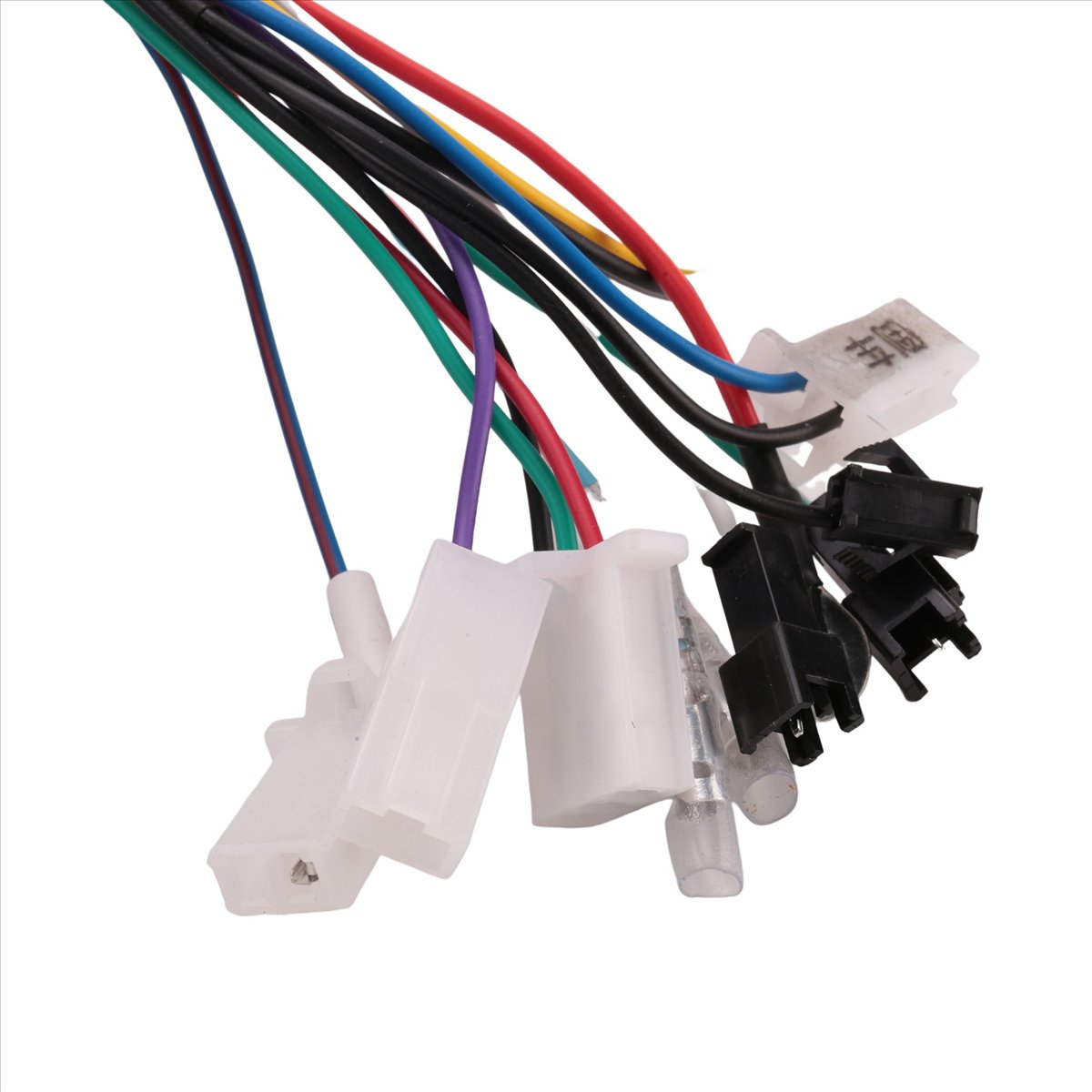
Figure 4: Various signal connectors for throttle, brake, display, and other functions.
Installation Steps
- Mount the controller securely in a protected area on your e-bike, ensuring good airflow for cooling. The ribbed side (heat sink) should be exposed if possible (see Figure 5).
- Connect the motor phase wires (Green, Blue, Yellow) to the corresponding motor wires.
- Connect the motor Hall sensor wires.
- Connect the throttle, brake levers, and display unit.
- Connect the ignition/electric lock wires.
- Finally, connect the main battery power wires (thick red and black) to your battery.
- If your motor requires self-learning, connect the self-learning wires (usually two white wires) briefly. The motor should spin. If it spins in the wrong direction, disconnect and reconnect them. Once the motor spins correctly, disconnect the self-learning wires.
- Double-check all connections for security and proper insulation.
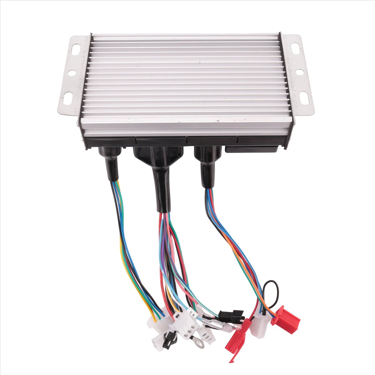
Figure 5: Rear view of the controller, highlighting the heat sink for thermal management.
Operating Instructions
- Ensure all connections are correct and secure.
- Turn on the e-bike's power (usually via a key switch or battery button).
- If equipped, turn on your e-bike display.
- Gently twist the throttle to engage the motor. The sine wave controller provides a smooth and quiet start.
- Apply brakes to cut power to the motor.
- Always operate your e-bike safely and in accordance with local regulations.
Maintenance
- Regularly inspect all wiring connections for signs of wear, corrosion, or looseness.
- Keep the controller clean and free from dust, dirt, and moisture. Use a dry cloth for cleaning.
- Ensure the controller's heat sink (ribbed metal part) is not obstructed to allow for proper cooling.
- Avoid exposing the controller to extreme temperatures or harsh chemicals.
Troubleshooting
If you encounter issues with your controller, refer to the following common troubleshooting steps:
- No Power to Motor/Display:
- Check battery charge level.
- Verify main battery power connections (thick red/black wires) are secure.
- Ensure the ignition/electric lock wire is properly connected and activated.
- Inspect all fuses in the e-bike system.
- Motor Not Spinning/Erratic Behavior:
- Check motor phase wire connections (Green, Blue, Yellow).
- Verify motor Hall sensor wire connections.
- Ensure throttle is correctly connected and functioning.
- If applicable, perform the self-learning procedure again.
- Check for any error codes on your e-bike display.
- Brakes Not Cutting Power:
- Inspect brake lever cut-off sensor connections.
- Ensure brake levers are properly adjusted.
If the problem persists after following these steps, contact customer support.
User Tips
- For optimal performance, ensure your motor is compatible with a sine wave controller.
- When replacing an old controller, carefully label all wires before disconnecting to simplify the new installation.
- Consider using waterproof connectors or sealing existing connections with electrical tape for added protection against the elements.
Warranty and Support
For any questions, technical assistance, or warranty claims, please contact the seller directly through the platform where the product was purchased. Provide your order number and a detailed description of the issue for prompt support.