1. Introduction
The ESP32-P4-NANO is a high-performance development board built around the ESP32-P4 chip. It integrates RISC-V dual-core and single-core processors, offering robust processing capabilities. This board is designed with rich Human-Machine Interfaces, including MIPI-CSI with an integrated Image Signal Processor and a MIPI-DSI interface. It supports a wide array of standard peripherals such as SPI, I2S, I2C, LED PWM, MCPWM, RMT, ADC, UART, and TWAI. High-speed connectivity is facilitated through USB OTG 2.0 HS, Ethernet, and SDIO Host 3.0.
The ESP32-P4 chip also incorporates a Digital Signature Peripheral and a dedicated Key Management Unit, ensuring enhanced data security. The ESP32-P4-NANO is ideal for applications requiring high performance, advanced security, sophisticated Human-Machine Interfaces, efficient edge computing, and extensive I/O connectivity.

2. Key Features
- High-performance MCU: Features RISC-V 32-bit dual-core and single-core processors.
- Memory: Includes 128 KB HP ROM, 16 KB LP ROM, 768 KB HP L2MEM, 32 KB LP SRAM, 8 KB TCM, 32MB PSRAM (in-package), and onboard 16MB Nor Flash.
- Image and Voice Processing: Powerful capabilities with interfaces like JPEG Codec, Pixel Processing Accelerator, Image Signal Processor, and H264 encoder.
- Connectivity: Onboard ESP32-C6-MINI module extends 2.4GHz Wi-Fi 6 and Bluetooth 5/BLE via SDIO interface. Includes a 100Mbps RJ45 Ethernet port.
- Interfaces: MIPI-CSI (2-lane), MIPI-DSI (2-lane), USB 2.0 OTG, SDIO 3.0 (TF card slot), microphone, speaker header, and RTC battery header.
- GPIO: 2*2*13 GPIO headers with 28 programmable GPIOs.
- Security: Secure Boot, Flash Encryption, cryptographic accelerators, TRNG, Access Permission Management, and Privilege Separation.
- Power Options: Supports external 5V power supply and optional Power over Ethernet (PoE) module.
ESP32-P4 high-performance MCU
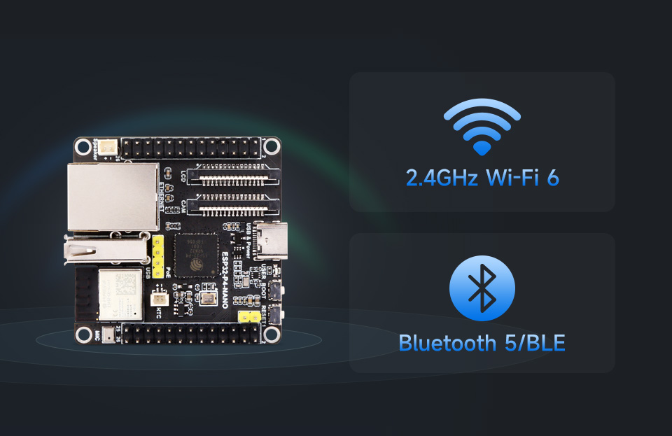
Integrated Wi-Fi 6 and Bluetooth 5/BLE
3. Specifications
3.1. ESP32-P4-NANO Board
| Feature | Description |
|---|---|
| MCU | ESP32-P4 (RISC-V 32-bit dual-core and single-core processors) |
| PSRAM | 32MB (in-package) |
| Nor Flash | 16MB (onboard) |
| Wi-Fi | 2.4GHz Wi-Fi 6 (via ESP32-C6-MINI) |
| Bluetooth | Bluetooth 5/BLE (via ESP32-C6-MINI) |
| Ethernet | 100Mbps RJ45 port |
| USB | USB Type-C (power, program, debug), USB OTG 2.0 HS (Type-A port) |
| Display Interface | MIPI DSI 2-lane |
| Camera Interface | MIPI CSI 2-lane |
| Storage | TF card slot (SDIO 3.0 interface) |
| Audio | Speaker header (MX1.25 2P, supports 8Ω 2W speaker), Onboard microphone |
| GPIO | 2*2*13 headers, 28 programmable GPIOs |
| Dimensions | 50.00mm × 50.00mm |
3.2. 10.1-inch DSI Capacitive Touch Display (Included in KIT-D)
| Feature | Specification |
|---|---|
| Resolution | 800 × 1280 (H×V) |
| Outline Dimension | 147.0 × 239.0 (mm) |
| Communication Interface | MIPI 2-lane (supports ESP32-P4, RK3576, RK3506) |
| Display Area | 135.96 × 217.18 (mm) |
| Pixel Pitch | 0.1175 × 0.1088 (mm) |
| Brightness | 500cd/m² (customization for 1000cd/m² high brightness available) |
| Contrast Ratio | 800:1 |
| Touch Chip | GT9271 |
| Operation Temperature | -10℃ ~ 50℃ |
3.3. RPi Camera (B) (Included in KIT-A, KIT-C, KIT-D)
| Feature | Specification |
|---|---|
| Sensor | OV5647 |
| Pixels | 5MP |
| CMOS Size | 1/4 inch |
| Aperture | F2.0 |
| Focal Length | 6mm |
| Field of View | 60.6° |
| Night Vision | Not supported |
| Focusing | Manual Focus |
4. Package Content
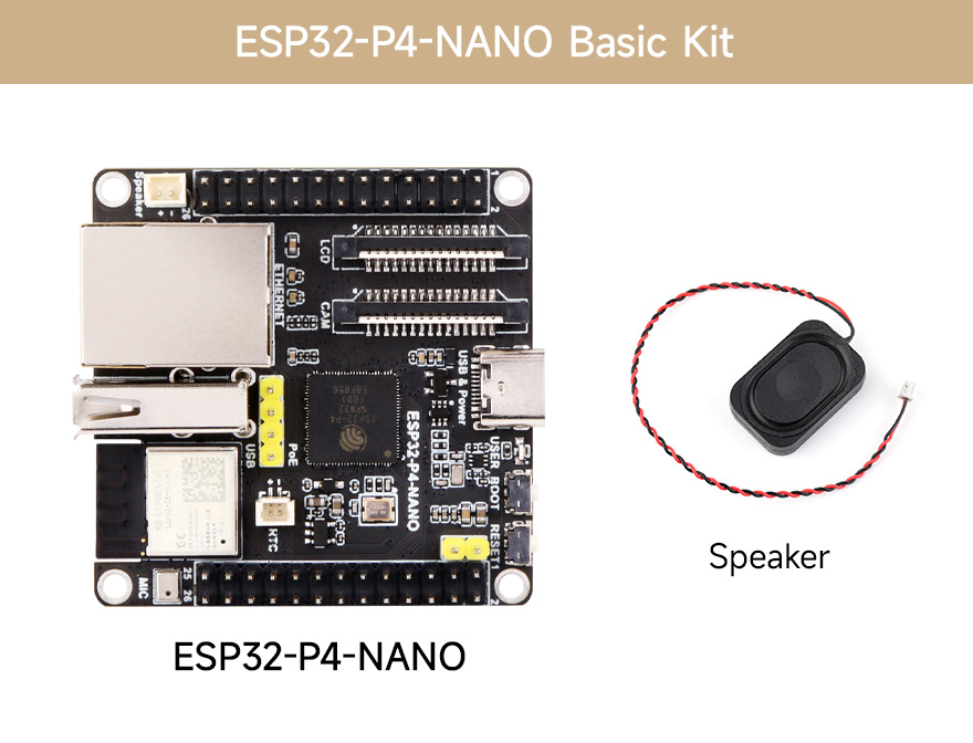
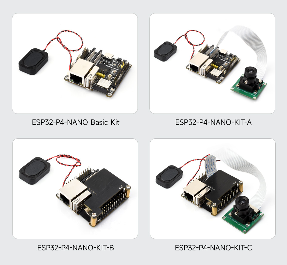
4.1. ESP32-P4-NANO Basic Kit
- ESP32-P4-NANO x1
- 8Ω 2W speaker x1
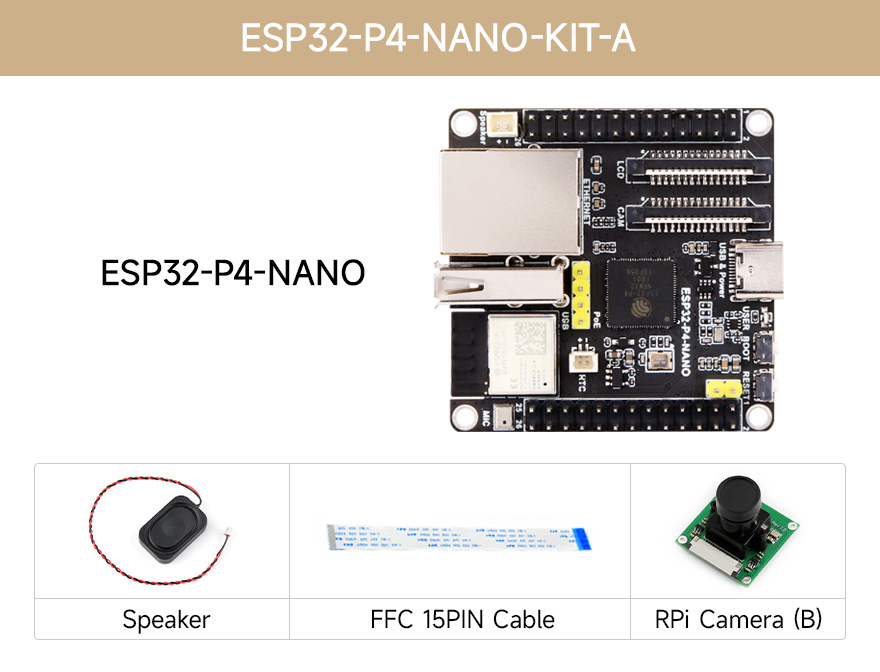
4.2. ESP32-P4-NANO-KIT-A
- ESP32-P4-NANO x1
- RPi Camera (B) x1
- 8Ω 2W speaker x1
- FFC 15PIN cable x1
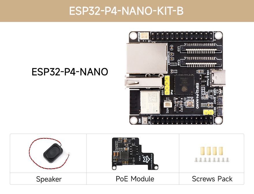
4.3. ESP32-P4-NANO-KIT-B
- ESP32-P4-NANO x1
- PoE module x1
- 8Ω 2W speaker x1
- Screws pack x1
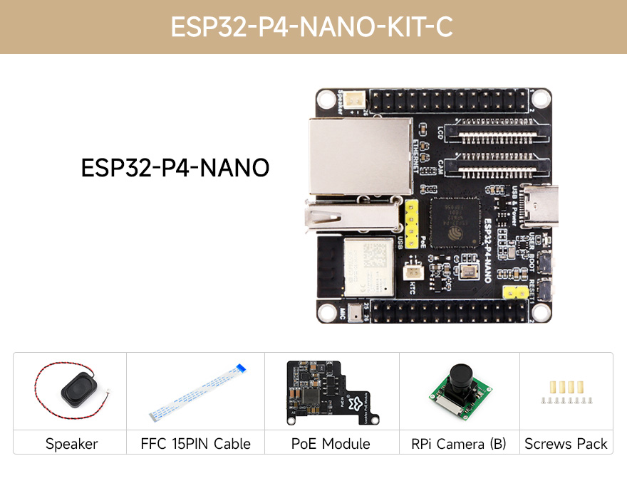
4.4. ESP32-P4-NANO-KIT-C
- ESP32-P4-NANO x1
- PoE module x1
- 8Ω 2W speaker x1
- FFC 15PIN cable x1
- RPi Camera (B) x1
- Screws pack x1
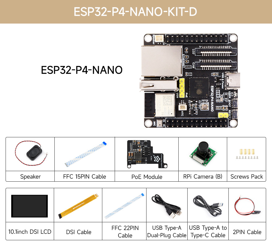
4.5. ESP32-P4-NANO-KIT-D
- 10.1inch DSI LCD x1
- ESP32-P4-NANO x1
- PoE module x1
- Screws pack x1
- USB Type-A dual-plug cable x1
- USB Type-A to Type-C cable ~1m x1
- RPi Camera (B) x1
- MIPI-DSI-Cable x1
- FFC 15PIN cable x1
- FFC 22PIN cable x1
- 8Ω 2W speaker x1
- SH1.0 2PIN cable x1
5. Setup and Installation
5.1. Board Layout and Components
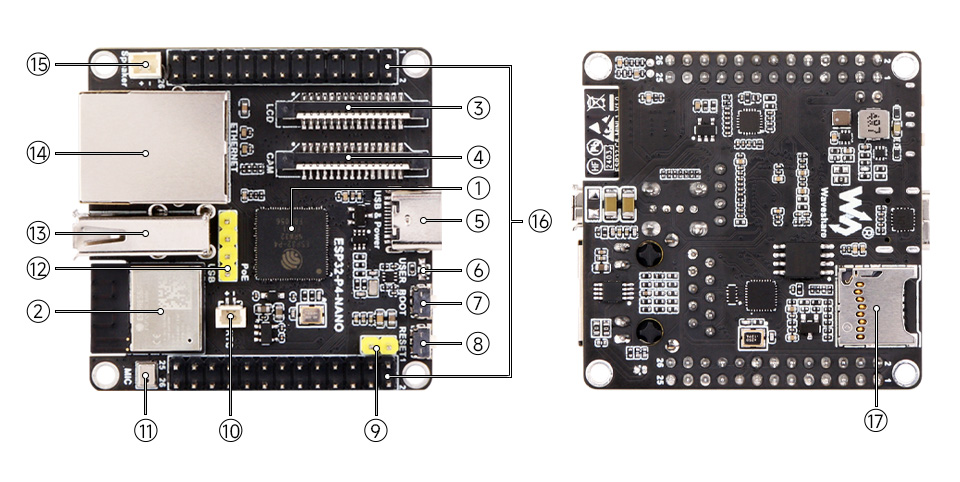
- ESP32-P4NRW32: ESP32-P4 chip with 32MB PSRAM.
- ESP32-C6-MINI-1: SDIO interface protocol, extending Wi-Fi 6 and Bluetooth 5 for ESP32-P4-NANO.
- Display interface: MIPI 2-lane.
- Camera interface: MIPI 2-lane.
- USB Type-C connector: For power supply, program burning, and debugging.
- USER-LED: Power supply indicator.
- BOOT button: Press it when powering on or resetting to enter download mode.
- RESET button.
- PoE module / external power supply header: For connecting external 5V power supply or PoE module power supply.
- RTC battery header: For connecting rechargeable RTC battery (supports rechargeable RTC batteries only).
- Onboard microphone.
- PoE module header.
- Type-A Port: USB OTG 2.0 High Speed port.
- RJ45 100M Ethernet port.
- Speaker header: MX1.25 2P connector, supports 8Ω 2W speaker.
- GPIO header.
- TF card slot: SDIO 3.0 interface protocol.
5.2. Pin Definition
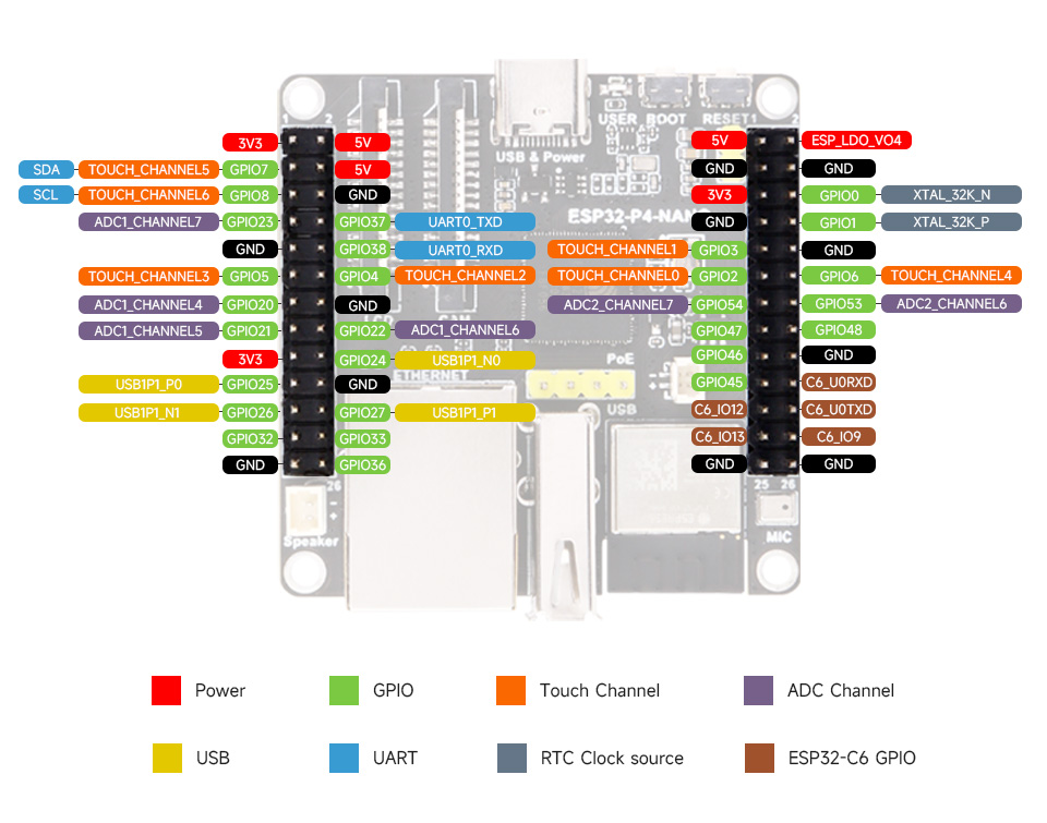
The pinout diagram above illustrates the functions of each pin on the ESP32-P4-NANO board. Refer to this diagram for connecting external components and peripherals.
5.3. Connecting Peripherals
The ESP32-P4-NANO supports various peripherals. Below are examples of common connections:
- Speaker: Connect an 8Ω 2W speaker to the dedicated speaker header (MX1.25 2P).
- Camera: Connect an RPi Camera (B) to the MIPI CSI 2-lane camera interface using the provided FFC 15PIN cable.
- Display: For KIT-D, connect the 10.1-inch DSI LCD to the MIPI DSI 2-lane display interface using the MIPI-DSI-Cable.
- PoE Module (Optional): If using a PoE module, attach it to the dedicated PoE module header. This allows for power and network connectivity via a single Ethernet cable from an 802.3af-compliant router or switch.
Example connection with display, camera, and speaker
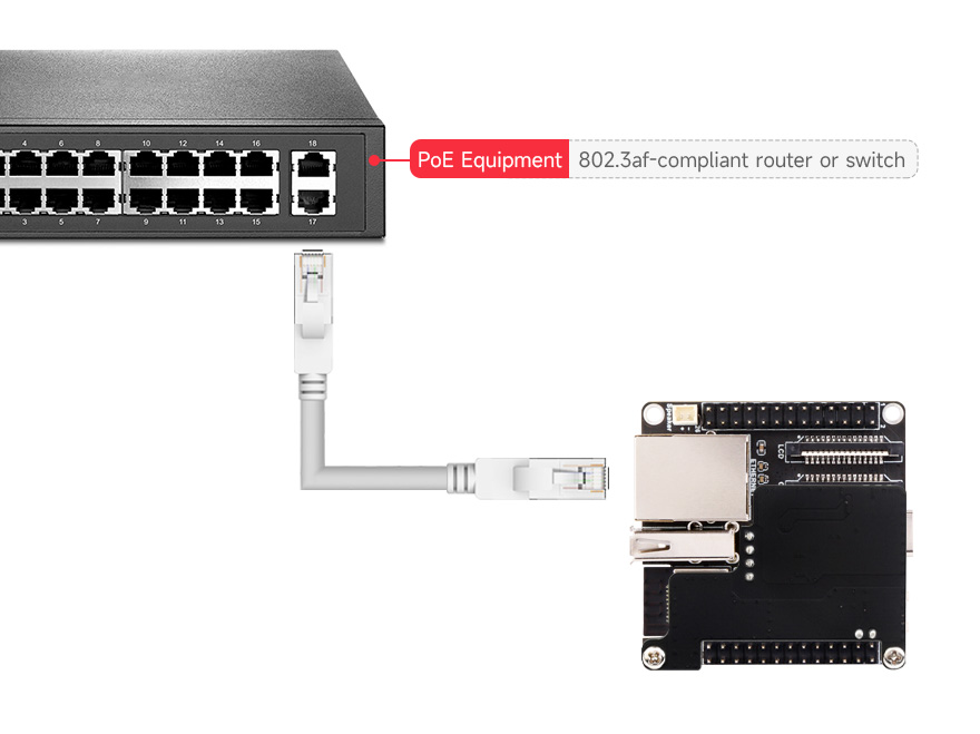
PoE connection diagram (PoE module optional, switch not included)
5.4. Powering the Board
The board can be powered via the USB Type-C connector or through the PoE module header if a PoE module is installed. Ensure a stable 5V power supply is used.
6. Operating Instructions
6.1. Initial Power-Up
Connect the ESP32-P4-NANO to your computer using a USB Type-C cable. The USER-LED should illuminate, indicating power. The board will typically enter a default operating mode or wait for firmware upload.
6.2. Firmware Upload and Debugging
To upload custom firmware or debug your applications, connect the USB Type-C port to your development machine. Press and hold the BOOT button while powering on or resetting the board to enter download mode. Release the BOOT button once in download mode. Refer to the Waveshare Wiki for detailed instructions on setting up your development environment and using Espressif's tools for programming.
6.3. Using Interfaces
- Wi-Fi and Bluetooth: Utilize the ESP32-C6-MINI module for wireless communication. Programming examples and libraries are available through the Espressif SDK.
- Ethernet: Connect an Ethernet cable to the RJ45 port for wired network access.
- Camera and Display: Program the MIPI-CSI and MIPI-DSI interfaces to capture images from the camera and display content on compatible screens.
- GPIO: The programmable GPIOs can be configured for various digital and analog functions, including I2C, SPI, UART, and more, depending on your application needs.
7. Maintenance
- Cleaning: Keep the board clean and free from dust and debris. Use a soft, dry brush or compressed air for cleaning. Avoid using liquids or solvents.
- Storage: Store the board in a dry, anti-static environment when not in use.
- Handling: Handle the board by its edges to avoid touching components, especially the sensitive chip areas. Static electricity can damage electronic components.
- Power Supply: Always use a stable and appropriate power supply (5V). Incorrect voltage can damage the board.
8. Troubleshooting
- Board not powering on: Ensure the USB Type-C cable is securely connected and the power source is active. If using PoE, verify the PoE module is correctly installed and the Ethernet source provides power.
- Firmware upload failure: Make sure the board is in download mode (press BOOT button during power-up/reset). Check your development environment setup and cable connection.
- Peripheral not detected: Verify all connections are secure and correctly wired according to the pin definition. Ensure the correct drivers and software configurations are applied in your code.
- Wi-Fi/Bluetooth issues: Check antenna connections (if external) and ensure the ESP32-C6-MINI module is properly communicating with the ESP32-P4. Verify software configuration for wireless protocols.
- System instability: Ensure adequate power supply. Overheating can cause instability; ensure proper ventilation if running demanding applications.
9. User Tips
- Start with examples: Begin by running official examples provided in the Waveshare Wiki or Espressif SDK to familiarize yourself with the board's functionalities.
- Power considerations: For projects requiring significant power, especially with multiple peripherals, consider using the PoE module or a robust 5V power adapter instead of relying solely on USB power from a computer.
- Community support: Engage with the ESP32 developer community for additional resources, project ideas, and troubleshooting assistance.
10. Support and Resources
For detailed technical documentation, programming guides, example code, and further support, please visit the official Waveshare Wiki page for the ESP32-P4-NANO:
www.waveshare.com/wiki/ESP32-P4-NANO