
1. Introduction
This manual describes the assembly, installation, operation, and troubleshooting of the Sumry Hybrid Inverter. It combines the functions of an inverter, solar charger, and battery charger to provide uninterruptible power support. The comprehensive LCD display allows for user-configurable settings such as battery charging current, AC/solar charger priority, and acceptable input voltage for various applications.
1.1 Key Features
- Pure sine wave output for sensitive appliances.
- Configurable input voltage range for home appliances and personal computers.
- Configurable battery charging current.
- Configurable AC/Solar Charger priority.
- Compatible with mains voltage or generator power.
- Automatic restart upon AC recovery.
- Overload, over-temperature, and short circuit protection.
- Smart battery charger design to optimize battery performance.
- Cold start function.
- Built-in 120A MPPT solar charge controller.
- High PV input voltage range (60-500VDC).
- Built-in anti-dust kit for harsh environments.
- Dual output capability.
- One-key restoration to factory settings.
- Built-in Lithium battery automatic activation.
- Dual communication ports for Battery communication and Wifi communication.
1.2 Basic System Architecture
The inverter/charger can be integrated into a system with solar panels, a generator or utility power, and external battery packs to power home appliances. Consult with your system integrator for specific configurations.

2. Safety Instructions
WARNING: This chapter contains important safety and operating instructions. Read and keep this manual for future reference.
- Before using the unit, read all instructions and cautionary markings on the unit, the batteries, and all appropriate sections of this manual.
- CAUTION -- To reduce risk of injury, charge only deep-cycle lead acid type rechargeable batteries. Other types of batteries may burst, causing personal injury and damage.
- Do not disassemble the unit. Take it to a qualified service center when service or repair is required. Incorrect re-assembly may result in a risk of electric shock or fire.
- To reduce risk of electric shock, disconnect all wirings before attempting any maintenance or cleaning. Turning off the unit will not reduce this risk.
- CAUTION – Only qualified personnel can install this device with battery.
- NEVER charge a frozen battery.
- For optimum operation of this inverter/charger, please follow required spec to select appropriate cable size. It's very important to correctly operate this inverter/charger.
- Be very cautious when working with metal tools on or around batteries. A potential risk exists to drop a tool to spark or short circuit batteries or other electrical parts and could cause an explosion.
- Please strictly follow installation procedure when you want to disconnect AC or DC terminals. Please refer to INSTALLATION section of this manual for the details.
- One piece of 150A fuse is provided as over-current protection for the battery supply.
- GROUNDING INSTRUCTIONS - This inverter/charger should be connected to a permanent grounded wiring system. Be sure to comply with local requirements and regulation to install this inverter.
- NEVER cause AC output and DC input short circuited. Do NOT connect to the mains when DC input short circuits.
- Warning!! Only qualified service persons are able to service this device. If errors still persist after following troubleshooting table, please send this inverter/charger back to local dealer or service center for maintenance.
3. Product Overview
The Sumry Hybrid Inverter features a user-friendly LCD display and various connection ports for seamless integration into your solar power system.

- 1. AC input
- 2. Main output
- 3. Second output
- 4. RS-232 communication port/Wifi-port
- 5. PV input
- 6. Battery input

4. Setup and Installation
4.1 Unpacking and Inspection
Before installation, carefully inspect the unit for any damage. The package should contain the inverter unit and a user manual.
4.2 Mounting the Unit
Mount the inverter on a solid, non-combustible surface at eye level. Ensure a clearance of approximately 20 cm to the sides and 50 cm above and below for proper air circulation and heat dissipation. The ambient temperature should be between 0°C and 55°C. Use M6 screws for mounting.
4.3 Installation Steps
- Battery Connection: Install a circuit breaker between the battery and the inverter. For 3.6KW/4.2KW models, use a 24V battery; for 6.2KW models, use a 48V battery. After connecting the battery, close the circuit breaker and measure the voltage at the inverter's battery terminals.
- PV Connection: Install a circuit breaker between the PV input and the inverter. Ensure the battery voltage is normal. Connect the solar panels, then close the PV input circuit breaker. The inverter display will light up and begin charging.
- Inverter Startup: Press the button on the bottom right corner of the inverter to start the machine. Verify a 220V/230V/240V AC voltage output from the inverter.
- AC Input/Output Connection: Install a circuit breaker between the AC input and the inverter, and another between the inverter's output and the load. Turn on both AC input and output circuit breakers. Connect the machine to the mains, then turn off the mains input circuit breaker, and after 2 minutes, turn off the inverter's output circuit breaker. This completes the installation procedure.
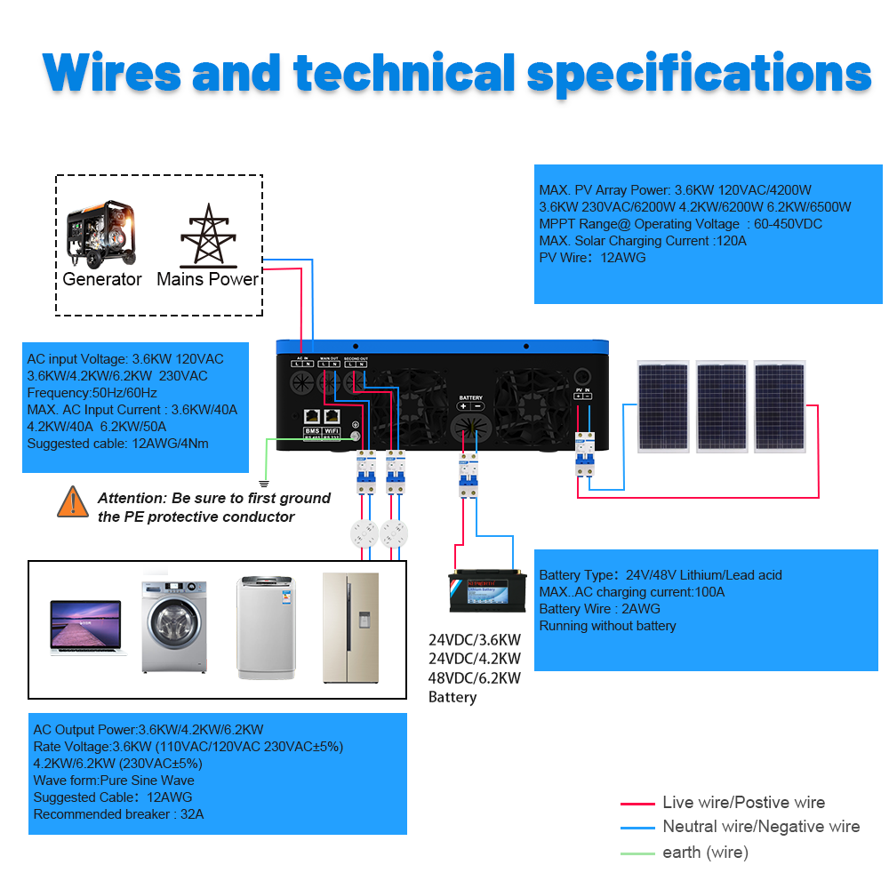
4.4 Circuit Breaker Specifications
- For 3.6KW machine:
- Battery to Inverter: 2P80A
- Photovoltaic Input to Inverter: 2P20A
- Utility Input to Inverter: 2P63A
- Inverter Output: 2P30A
- For 4.2KW machine:
- Battery to Inverter: 2P200A
- Photovoltaic Input to Inverter: 2P20A
- Utility Input to Inverter: 2P40A
- Inverter Output: 2P20A
- For 6.2KW machine:
- Battery to Inverter: 2P150A
- Photovoltaic Input to Inverter: 2P20A
- Utility Input to Inverter: 2P63A
- Inverter Output: 2P25A

4.5 Battery Connection Details
For safety and compliance, install a separate DC over-current protector or disconnect device between the battery and inverter. Refer to the table below for recommended cable sizes and torque values.
WARNING! All wiring must be performed by qualified personnel.
WARNING! It's very important for system safety and efficient operation to use appropriate cable for battery connection. To reduce risk of injury, please use the proper recommended cable as below.
| Model | Wire Size | Cable (mm²) | Torque value (max) |
|---|---|---|---|
| 3.6KW/4.2KW/6.2KW | 1 x 2AWG | 25 | 2 Nm |
To connect: Remove 18mm insulation from positive and negative conductors. Use bootlace ferrules with a proper crimping tool. Connect all battery packs as shown in the diagram below. Insert battery wires flatly into inverter connectors and tighten bolts to 2 Nm clockwise. Ensure correct polarity.

WARNING: Shock Hazard. Installation must be performed with care due to high battery voltage in series.
CAUTION!! Before making the final DC connection or closing DC breaker/disconnector, be sure positive (+) must be connected to positive (+) and negative (-) must be connected to negative (-).
4.6 AC Input/Output Connection Details
Install a separate AC breaker between the inverter and the AC input power source. This ensures safe disconnection during maintenance and over-current protection. Recommended AC breaker specs: 32A for 3.6KW/4.2KW and 50A for 6.2KW.
CAUTION!! There are two terminal blocks with “IN” and “OUT” markings. Do NOT mis-connect input and output connectors.
WARNING! All wiring must be performed by qualified personnel.
| Model | Gauge | Cable (mm²) | Torque Value |
|---|---|---|---|
| 3.6KW/4.2KW | 12 AWG | 4 | 1.2 Nm |
| 6.2KW | 10 AWG | 6 | 1.2 Nm |
To connect: Open DC protector/disconnector. Remove 10mm insulation from conductors and shorten phase L and neutral conductor N by 3mm. Insert AC input wires according to polarities (L=brown/black, N=blue) and tighten screws. Repeat for AC output wires.
WARNING: Be sure that AC power source is disconnected before attempting to hardwire it to the unit.
Ensure all wires are securely connected. Note: Appliances like air conditioners require 2-3 minutes to restart to balance refrigerant gas. A power shortage and quick recovery can damage appliances. Check appliance manufacturer for time-delay function.
4.7 PV Connection Details
Install a DC circuit breaker between the inverter and PV modules. Refer to the table below for recommended cable sizes.
| Model | Wire Size | Cable (mm²) | Torque value (max) |
|---|---|---|---|
| 3.6KW/4.2KW/6.2KW | 1 x 12AWG | 4 | 1.2 Nm |
PV Module Selection
When selecting PV modules, consider the following:
- Open circuit Voltage (Voc) of PV modules must not exceed the max. PV array open circuit voltage of the inverter.
- Open circuit Voltage (Voc) of PV modules should be higher than the min. battery voltage.
| INVERTER MODEL | 3.6KW/4.2KW | 6.2KW |
|---|---|---|
| Max. PV Array Open Circuit Voltage | 500Vdc | |
| PV Array MPPT Voltage Range | 60Vdc~450Vdc | |
For example, with 250Wp PV modules, recommended configurations are provided in the full user manual (PDF).
4.8 Communication Connection
The inverter supports both Wi-Fi and GPRS cloud communication, as well as direct battery communication.
- Wi-Fi Cloud Communication (Optional): Use the supplied communication cable to connect the inverter to a Wi-Fi module. Download the APP and refer to the "Wi-Fi Plug Quick Installation Guideline" to set up the network and register. The inverter status can then be monitored via mobile app or webpage.
- GPRS Cloud Communication (Optional): Use the supplied communication cable to connect the inverter to a GPRS module, and apply external power to the GPRS module. Download the APP and refer to the “GPRS RTU Quick Installation Guideline" to set up the network and register. The inverter status can then be monitored via mobile app or webpage.
- Battery Communication: The communication between the battery and the inverter is established via the battery communication interface (RS485 for lithium battery BMS communication, supporting PACE or PYLONTECH protocols), allowing for data exchange.


After all wirings are connected, replace the bottom cover by screwing in the two screws.
5. Operation
5.1 Power ON/OFF
Once the unit is properly installed and batteries are connected, press the On/Off switch (located on the bottom of the case) to turn on the unit.
5.2 Operation and Display Panel
The front panel of the inverter features three indicators, four function keys, and an LCD display to show operating status and input/output power information.

LED Indicator Messages
| LED Indicator | Color | Messages |
|---|---|---|
| INV/AC | Green | Solid On: Output is powered by utility in Line mode. Flashing: Output is powered by battery or PV in battery mode. |
| CHG | Green | Solid On: Battery is fully charged. Flashing: Battery is charging. |
| FAULT | Red | Solid On: Fault occurs in the inverter. Flashing: Warning condition occurs in the inverter. |
Function Keys
| Function Key | Description |
|---|---|
| ESC | To exit setting mode |
| UP | To go to previous selection |
| DOWN | To go to next selection |
| ENTER | To confirm the selection in setting mode or enter setting mode |
5.3 LCD Display Icons
The LCD display shows various icons to indicate the inverter's status and operational parameters. These include input source information (AC, PV), output information (voltage, frequency, load), battery information, and mode of operation (unit connected to mains, PV panel, or load supplied by utility power).
5.4 LCD Setting
To enter setting mode, press and hold the ENTER button for 3 seconds. Use UP/DOWN buttons to navigate and ENTER to confirm selections. ESC exits the setting mode. Various parameters can be configured, including output source priority, maximum charging current, AC input voltage range, battery type, auto restart options, output frequency, output voltage, and battery equalization settings.
Operating Mode Description
The inverter supports versatile working modes, allowing customization of power input and output priorities. These include:
- Charging Modes: Only Solar, Mains First, Solar First, Mains & Solar.
- Output Modes: Solar First, Utility First, SBU First.

5.5 Battery Equalization
The equalization function helps reverse negative chemical effects like stratification and removes sulfate crystals, optimizing battery capacity and longevity. It's recommended to equalize batteries periodically.
How to Apply Equalization Function
Enable battery equalization in LCD setting program 30. Then, you can apply it by setting the equalization interval in program 35 or by activating it immediately in program 36.
When to Equalize
In the float stage, when the set equalization interval is reached or equalization is activated immediately, the controller will enter the Equalize stage.
During the Equalize stage, the controller charges the battery until it reaches the equalization voltage. If the battery voltage is still low after the equalized time expires, the charge controller will extend the time until the battery reaches the target voltage. If it still doesn't reach the voltage after the timeout, equalization stops, and the system returns to float stage.
6. Maintenance
6.1 Clearance and Maintenance for Anti-Dust Kit
The inverter comes with a pre-installed anti-dust kit to protect against dust and improve reliability. The inverter automatically detects this kit and adjusts internal thermal sensors for optimal temperature management.
Cleaning Procedure:
- Loosen the screws on the top of the inverter in a counterclockwise direction.
- Remove the dustproof case and take out the air filter foam.
- Clean the air filter foam and dustproof case.
- Re-assemble the dust-kit back into the inverter.
NOTICE: The anti-dust kit should be cleaned every one month.
7. Troubleshooting
This section provides guidance for common issues. For persistent problems, contact a qualified service center.
| Problem | LCD/LED/Buzzer Indication | Explanation / Possible Cause | What to do |
|---|---|---|---|
| Unit shuts down automatically during startup process. | LCD/LEDs and buzzer active for 3 seconds then off. | Battery voltage is too low (<1.91V/Cell) | 1. Re-charge battery. 2. Replace battery. |
| No response after power on. | No indication. | 1. Battery voltage is far too low (<1.4V/Cell). 2. Internal fuse tripped. | 1. Contact repair center for fuse replacement. 2. Re-charge battery. 3. Replace battery. |
| Mains exist but the unit works in battery mode. | Input voltage displayed as 0 on LCD, green LED flashing. | Input protector is tripped. | Check if AC breaker is tripped and AC wiring is connected well. |
| Mains exist but the unit works in battery mode. | Green LED is flashing. | Insufficient quality of AC power (Shore or Generator). | 1. Check if AC wires are too thin/long. 2. Check generator (if applied) or input voltage range setting. |
| Mains exist but the unit works in battery mode. | Green LED is flashing. | Set "Solar First" as the priority of output source. | Change output source priority to Utility first. |
| When the unit is turned on, internal relay is switched on and off repeatedly. | LCD display and LEDs are flashing. | Battery is disconnected. | Check if battery wires are connected well. |
| Buzzer beeps continuously and red LED is on. | Fault code 07 | Overload error. Inverter is overload 110% and time is up. | Reduce the connected load by switching off some equipment. |
| Buzzer beeps continuously and red LED is on. | Fault code 05 | Output short circuited. | Check if wiring is connected well and remove abnormal load. |
| Buzzer beeps continuously and red LED is on. | Fault code 02 | Temperature of internal converter component is over 120°C. Internal temperature of inverter component is over 100°C. | Check whether the air flow of the unit is blocked or whether the ambient temperature is too high. |
| Buzzer beeps continuously and red LED is on. | Fault code 03 | Battery is over-charged. The battery voltage is too high. | Return to repair center. Check if spec and quantity of batteries meet requirements. |
| Buzzer beeps continuously and red LED is on. | Fault code 01 | Fan fault. | Replace the fan. |
| Buzzer beeps continuously and red LED is on. | Fault code 06/58 | Output abnormal (Inverter voltage below 190Vac or higher than 260Vac). | 1. Reduce the connected load. 2. Return to repair center. |
| Buzzer beeps continuously and red LED is on. | Fault code 08/09/53/57 | Internal components failed. | Return to repair center. |
| Buzzer beeps continuously and red LED is on. | Fault code 51 | Over current or surge. | Restart the unit, if the error happens again, please return to repair center. |
| Buzzer beeps continuously and red LED is on. | Fault code 52 | Bus voltage is too low. | Restart the unit, if the error happens again, please return to repair center. |
| Buzzer beeps continuously and red LED is on. | Fault code 55 | Output voltage is unbalanced. | Restart the unit, if the error happens again, please return to repair center. |
Warning Indicator
The inverter provides various warning codes and audible alarms to indicate potential issues. Refer to the full user manual (PDF) for a complete list of warning codes and their corresponding actions.
8. Specifications
Detailed technical specifications for the Sumry Hybrid Inverter are provided below. For a comprehensive list, please refer to the full user manual (PDF).
8.1 Line Mode Specifications
| Parameter | 3.6KW | 4.2KW | 6.2KW |
|---|---|---|---|
| Input Voltage Waveform | Sinusoidal (utility or generator) | ||
| Nominal Input Voltage | 230Vac | ||
| Low Loss Voltage | 170Vac±7V (UPS); 90Vac±7V (Appliances) | ||
| Low Loss Return Voltage | 180Vac±7V (UPS); 100Vac±7V (Appliances) | ||
| High Loss Voltage | 280Vac±7V | ||
| High Loss Return Voltage | 270Vac±7V | ||
| Max AC Input Voltage | 300Vac | ||
| Nominal Input Frequency | 50Hz / 60Hz (Auto detection) | ||
| Low Loss Frequency | 40±1Hz | ||
| Low Loss Return Frequency | 42±1Hz | ||
| High Loss Frequency | 65±1Hz | ||
| High Loss Return Frequency | 63±1Hz | ||
| Output Short Circuit Protection | Circuit Breaker | ||
| Efficiency (Line Mode) | >95% (Rated R load, battery full charged) | ||
| Transfer Time | 10ms typical (UPS); 20ms typical (Appliances) | ||
8.2 Inverter Mode Specifications
| Parameter | 3.6KW | 4.2KW | 6.2KW |
|---|---|---|---|
| Rated Output Power | 3.6KW | 4.2KW | 6.2KW |
| Output Voltage Waveform | Pure Sine Wave | ||
| Output Voltage Regulation | 230Vac±5% | ||
| Output Frequency | 50Hz | ||
| Peak Efficiency | 93% | ||
| Overload Protection | 3s@≥150% load; 5s@101%~150% load | ||
| Surge Capacity | 2* rated power for 5 seconds | ||
| Nominal DC Input Voltage | 24Vdc | 48Vdc | |
| Cold Start Voltage | 23.0Vdc | 46.0Vdc | |
| Low DC Warning Voltage @load < 50% | 22.0Vdc | 44.0Vdc | |
| Low DC Warning Voltage @load ≥ 50% | 21.0Vdc | 42.0Vdc | |
| Low DC Warning Return Voltage @load < 50% | 22.5Vdc | 45.0Vdc | |
| Low DC Warning Return Voltage @load ≥ 50% | 22.0Vdc | 44.0Vdc | |
| Low DC Cut-off Voltage @load < 50% | 20.5Vdc | 41.0Vdc | |
| Low DC Cut-off Voltage @load ≥ 50% | 20.0Vdc | 40.0Vdc | |
| High DC Recovery Voltage | 32Vdc | 62Vdc | |
| High DC Cut-off Voltage | 33Vdc | 63Vdc | |
| No Load Power Consumption | 30W | 35W | 50W |
8.3 Two Load Output Power
| INVERTER MODEL | 3.6KW | 4.2KW | 6.2KW |
|---|---|---|---|
| Full Load | 3600W | 4200W | 6200W |
| Maximum Main Load | 3600W | 4200W | 6200W |
| Maximum Second Load (battery model) | 1200W | 1400W | 2066W |
| Main Load Cut Off Voltage | 26VDC | 52VDC | |
| Main Load Return Voltage | 27VDC | 54VDC | |
8.4 MPPT Solar Charging Mode
| INVERTER MODEL | 3.6KW | 4.2KW | 6.2KW |
|---|---|---|---|
| Max. PV Array Power | 6200W | 6500W | |
| Nominal PV Voltage | 240Vdc | 360Vdc | |
| PV Array MPPT Voltage Range | 60Vdc~500Vdc | ||
| Max. PV Array Open Circuit Voltage | 500Vdc | ||
| Max Charging Current (AC charger plus solar charger) | 120Amp | 120Amp | 120Amp |
8.5 Grid-Tie Operation
| INVERTER MODEL | 3.6KW | 4.2KW | 6.2KW |
|---|---|---|---|
| Nominal Output Voltage | 220/230/240 VAC | ||
| Feed-in Grid Voltage Range | 195~253VAC | ||
| Feed-in Grid Frequency Range | 49~51±1Hz / 59~61±1Hz | ||
| Nominal Output Current | 15.7A | 18.2A | 26.9A |
| Power Factor Range | >0.99 | ||
| Maximum Conversion Efficiency (DC/AC) | 97% | ||
8.6 General Specifications
| Parameter | 3.6KW | 4.2KW | 6.2KW |
|---|---|---|---|
| Safety Certification | CE | ||
| Operating Temperature Range | -10°C to 50°C | ||
| Storage temperature | -15°C~60°C | ||
| Humidity | 5% to 95% Relative Humidity (Non-condensing) | ||
| Dimension (D*W*H), mm | 358×442×116 | ||
| Net Weight, kg | 8.0 | 8.0 | 8.9 |
8.7 Approximate Back-up Time Table
The following tables provide approximate back-up times based on load and battery capacity. Actual times may vary depending on battery quality, age, and type.
For 3.6KW/4.2KW Models (24Vdc)
| Load (W) | Backup Time @ 24Vdc 100Ah (min) | Backup Time @ 24Vdc 200Ah (min) |
|---|---|---|
| 300 | 449 | 1100 |
| 600 | 222 | 525 |
| 900 | 124 | 303 |
| 1200 | 95 | 227 |
| 1500 | 68 | 164 |
| 1800 | 56 | 126 |
| 2100 | 48 | 108 |
| 2400 | 35 | 94 |
| 2700 | 31 | 74 |
| 3200 | 28 | 67 |
| 3600 | 25 | 60 |
| 4200 | 22 | 53 |
For 6.2KW Models (48Vdc)
| Load (W) | Backup Time @ 48Vdc 100Ah (min) | Backup Time @ 48Vdc 200Ah (min) |
|---|---|---|
| 500 | 613 | 1288 |
| 1000 | 268 | 613 |
| 1500 | 158 | 402 |
| 2000 | 111 | 271 |
| 2500 | 90 | 215 |
| 3200 | 76 | 182 |
| 3500 | 65 | 141 |
| 4000 | 50 | 112 |
| 4500 | 44 | 100 |
| 5000 | 40 | 90 |
| 6200 | 36 | 80 |
9. User Tips
- Wi-Fi Monitoring: For remote monitoring and basic parameter setup via mobile app, ensure you purchase the optional Wi-Fi module and connect it to the RS232 communication port.
- Battery BMS Communication: If using lithium batteries with BMS communication, ensure your battery supports PACE or PYLONTECH protocols and connect via the RS485 port.
- Circuit Breaker Sizing: Always use the recommended circuit breaker sizes for battery, PV, AC input, and AC output connections to ensure safety and proper operation. Refer to the detailed specifications in this manual.
- Regular Maintenance: Clean the anti-dust kit monthly to maintain optimal performance and extend the inverter's lifespan, especially in harsh environments.
10. Warranty and Support
The Sumry Hybrid Inverter comes with a 1-year warranty. For any technical support, troubleshooting beyond the scope of this manual, or warranty claims, please contact your local dealer or authorized service center. Always ensure that only qualified personnel service the device to prevent electric shock or further damage.
A detailed user manual in PDF format is available for download. Click here to view the User Manual (PDF).
Video: Product unboxing, installation overview, and demonstration of charging a phone and boiling water using the inverter.