
1. Safety Instructions
WARNING: This chapter contains important safety and operating instructions. Read and keep this manual for future reference.
- Before using the unit, read all instructions and cautionary markings on the unit, the batteries and all appropriate sections of this manual.
- CAUTION --To reduce risk of injury, charge only deep-cycle lead acid type rechargeable batteries. Other types of batteries may burst, causing personal injury and damage.
- Do not disassemble the unit. Take it to a qualified service center when service or repair is required. Incorrect re-assembly may result in a risk of electric shock or fire.
- To reduce risk of electric shock, disconnect all wirings before attempting any maintenance or cleaning. Turning off the unit will not reduce this risk.
- CAUTION – Only qualified personnel can install this device with battery.
- NEVER charge a frozen battery.
- For optimum operation of this inverter/charger, please follow required spec to select appropriate cable size. It's very important to correctly operate this inverter/charger.
- Be very cautious when working with metal tools on or around batteries. A potential risk exists to drop a tool to spark or short circuit batteries or other electrical parts and could cause an explosion.
- Please strictly follow installation procedure when you want to disconnect AC or DC terminals. Please refer to INSTALLATION section of this manual for the details.
- One piece of 150A fuse is provided as over-current protection for the battery supply.
- GROUNDING INSTRUCTIONS -This inverter/charger should be connected to a permanent grounded wiring system. Be sure to comply with local requirements and regulation to install this inverter.
- NEVER cause AC output and DC input short circuited. Do NOT connect to the mains when DC input short circuits.
- Warning!! Only qualified service persons are able to service this device. If errors still persist after following troubleshooting table, please send this inverter/charger back to local dealer or service center for maintenance.
2. Product Overview
The Sumry 3.6kw Hybrid Solar Inverter is a multi-function inverter/charger, combining the capabilities of an inverter, solar charger, and battery charger to provide uninterruptible power support. It features a comprehensive LCD display for user-configurable settings such as battery charging current, AC/solar charger priority, and acceptable input voltage ranges.
2.1 Key Features
- Pure sine wave inverter output.
- Configurable input voltage range for home appliances and personal computers via LCD setting.
- Configurable battery charging current based on applications via LCD setting.
- Configurable AC/Solar Charger priority via LCD setting.
- Compatible with mains voltage or generator power.
- Auto restart while AC is recovering.
- Overload, over temperature, and short circuit protection.
- Smart battery charger design for optimized battery performance.
- Cold start function.
- Built-in 120A MPPT Solar charge controller, max 4200W solar charge.
- High PV input voltage range (60~500VDC).
- Built-in anti-dust kit for harsh environments.
- Dual output capability.
2.2 Product Video Overview
This video demonstrates the unboxing and basic setup of the Sumry Hybrid Solar Inverter, showcasing its physical features and connectivity options.
2.3 Basic System Architecture
The inverter/charger can be integrated into a system with a generator or utility power source and PV modules. It is designed to power various home and office appliances, including motor-type loads like refrigerators and air conditioners.

Diagram illustrating the basic connections for solar power, generator/utility, external battery packs, and home appliances to the inverter.
2.4 Product Components

Front and back view of the Sumry Hybrid Solar Inverter, highlighting the LCD display, status indicators, function buttons, and various input/output ports.
- LCD display
- Status indicator
- Charging indicator
- Fault indicator
- Function buttons
- Power on/off switch
- AC input
- Main output
- Second output
- Battery input
- PV input
- Anti dust kit
- RS-232 communication port/WiFi-port
- Circuit breaker
3. Setup (Installation)
3.1 Unpacking and Inspection
Before installation, carefully inspect the unit for any damage. The package should contain the inverter unit and a user manual.
3.2 Preparation
Before connecting any wiring, remove the bottom cover of the inverter by unscrewing the two screws.
3.3 Mounting the Unit
When selecting a mounting location, consider the following:
- Do not mount the inverter on flammable construction materials.
- Mount on a solid surface.
- Install at eye level for easy LCD display readability.
- Allow a clearance of approximately 20 cm to the sides and 50 cm above and below for proper air circulation and heat dissipation.
- Ensure the ambient temperature is between 0°C and 55°C for optimal operation.
- Mount vertically on the wall.
SUITABLE FOR MOUNTING ON CONCRETE OR OTHER NON-COMBUSTIBLE SURFACE ONLY.
Use M6 screws to install the unit.
3.4 Battery Connection
CAUTION: For safety and compliance, install a separate DC over-current protector or disconnect device between the battery and inverter. Refer to the typical amperage table for required fuse or breaker size.
WARNING! All wiring must be performed by qualified personnel.
WARNING! Use appropriate cable for battery connection to reduce risk of injury.
| Model | Wire Size | Cable (mm²) | Torque Value (max) |
|---|---|---|---|
| 3.6KW/6.2KW | 1 x 2AWG | 25 | 2 Nm |
Battery Connection Steps:
- Remove 18 mm of insulation sleeve from positive and negative conductors.
- Apply bootlace ferrules to the ends of positive and negative wires using a proper crimping tool.
- Connect all battery packs as shown in the diagram below.
- Insert battery wires flatly into inverter battery connectors. Tighten bolts with a torque of 2 Nm in a clockwise direction. Ensure correct polarity at both the battery and inverter/charger.

Detailed wiring diagram for battery connection to the inverter, including AC input, main output, second output, and PV input.
WARNING: Shock Hazard. Installation must be performed with care due to high battery voltage in series.
CAUTION!! Before making the final DC connection or closing DC breaker/disconnector, ensure positive (+) is connected to positive (+) and negative (-) is connected to negative (-).
3.5 AC Input/Output Connection
CAUTION!! Before connecting to AC input power source, install a separate AC breaker between the inverter and AC input power source. This ensures the inverter can be securely disconnected during maintenance and protected from overcurrent. Recommended AC breaker: 32A for 3.6KW and 50A for 6.2KW.
CAUTION!! Do not mis-connect input and output connectors. The unit has two terminal blocks marked “IN” and “OUT”.
WARNING! All wiring must be performed by qualified personnel.
| Model | Gauge | Cable (mm²) | Torque Value |
|---|---|---|---|
| 3.6KW | 12 AWG | 4 | 1.2 Nm |
| 6.2KW | 10 AWG | 6 | 1.2 Nm |
AC Input/Output Connection Steps:
- Before making AC input/output connection, ensure the DC protector or disconnector is open.
- Remove 10mm of insulation sleeve for six conductors. Shorten phase L and neutral conductor N by 3 mm.
- Insert AC input wires according to polarities indicated on the terminal block and tighten the terminal screws (L→LINE (brown or black), N→Neutral (blue)).
- Insert AC output wires according to polarities indicated on the terminal block and tighten the terminal screws (L→LINE (brown or black), N→Neutral (blue)).
- Ensure all wires are securely connected.
WARNING: Ensure the AC power source is disconnected before attempting to hardwire it to the unit.
3.6 PV Connection
CAUTION: Before connecting to PV modules, install a DC circuit breaker separately between the inverter and PV modules.
WARNING! Use appropriate cable for PV module connection for system safety and efficient operation.
| Model | Wire Size | Cable (mm²) | Torque Value (max) |
|---|---|---|---|
| 3.6KW/6.2KW | 1 x 12AWG | 4 | 1.2 Nm |
PV Module Selection Considerations:
- The Open Circuit Voltage (Voc) of PV modules must not exceed the maximum PV array open circuit voltage of the inverter.
- The Open Circuit Voltage (Voc) of PV modules should be higher than the minimum battery voltage.
| Inverter Model | 3.6KW | 6.2KW |
|---|---|---|
| Max. PV Array Open Circuit Voltage | 500Vdc | |
| PV Array MPPT Voltage Range | 60Vdc~450Vdc | 60Vdc~450Vdc |
PV Module Wire Connection Steps:
- Remove 10 mm of insulation sleeve from positive and negative conductors.
- Apply bootlace ferrules to the ends of positive and negative wires using a proper crimping tool.
- Check correct polarity of wire connection from PV modules and PV input connectors. Connect positive pole (+) to positive pole (+) of PV input connector, and negative pole (-) to negative pole (-). Recommended tool: 4mm blade screwdriver.
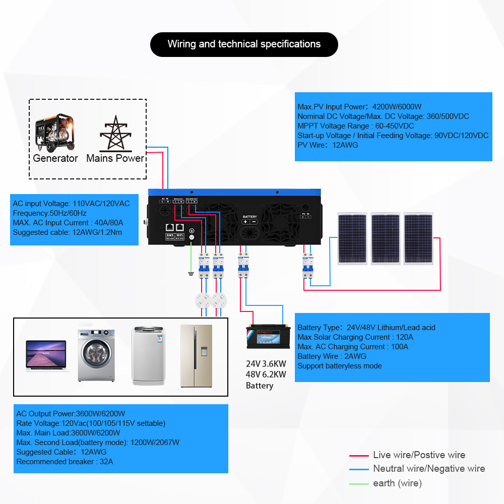
Diagram illustrating the sequence of connecting circuit breakers for battery, PV input, AC input, and inverter output.
3.7 Final Assembly
After connecting all wirings, replace the bottom cover by screwing the two screws back into place.
3.8 Communication Connection
The inverter features two communication ports:
- RS232 Communication Port: Used for WiFi module communication. The WiFi module enables remote monitoring via a mobile app or web page, and allows setting basic parameters. The WiFi module must be purchased separately.
- RS485 Communication Port: Used for lithium battery BMS communication. If using lithium battery BMS communication, ensure compatibility with PACE or PYLONTECH protocols.
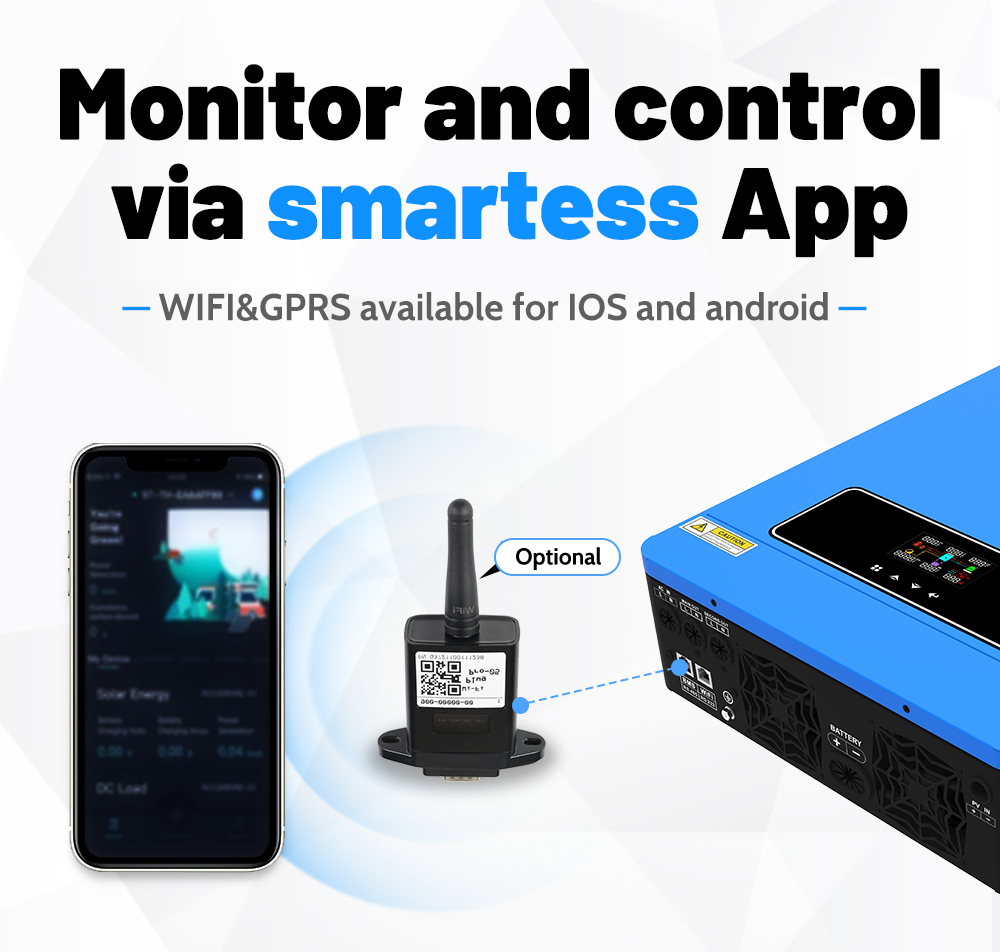
Diagram showing the RS232 and RS485 communication ports on the inverter and their connection to external modules.
4. Operation
4.1 Power ON/OFF
Once the unit is properly installed and batteries are connected, press the On/Off switch (located on the bottom of the case) to turn on the unit.
4.2 Operation and Display Panel
The front panel of the inverter includes three indicators, four function keys, and an LCD display to show operating status and input/output power information.
4.3 LCD Display Icons
The LCD display uses various icons to convey information about the inverter's status and operation. Below is a summary of common icons and their meanings:
| Indicator | Color/State | Message |
|---|---|---|
| INV/AC | Green Solid On | Output is powered by utility in Line mode. |
| Green Flashing | Output is powered by battery or PV in battery mode. | |
| CHG | Green Solid On | Battery is fully charged. |
| Green Flashing | Battery is charging. | |
| FAULT | Red Solid On | Fault occurs in the inverter. |
| Red Flashing | Warning condition occurs in the inverter. |
Function Keys:
- ESC: To exit setting mode.
- UP: To go to previous selection.
- DOWN: To go to next selection.
- ENTER: To confirm the selection in setting mode or enter setting mode.
4.4 LCD Setting
To enter setting mode, press and hold the ENTER button for 3 seconds. Use UP or DOWN buttons to select programs, and ENTER to confirm or ESC to exit.
Key settings include:
- Output Source Priority (Program 01): Configure whether the inverter prioritizes utility, solar, or a hybrid approach for powering loads. Options include: Utility First, Solar First, and SBU Priority.
- Maximum Charging Current (Program 02): Set the total charging current for solar and utility chargers (e.g., 10A, 20A, 30A, 40A, 50A, 60A).
- AC Input Voltage Range (Program 03): Select the acceptable AC input voltage range for appliances or UPS.
- Battery Type (Program 05): Choose the battery type (e.g., AGM, Flooded, User-Defined, Lithium).
- Auto Restart (Programs 06, 07): Enable or disable auto restart after overload or over temperature.
- Output Frequency (Program 09): Set to 50Hz or 60Hz.
- Output Voltage (Program 10): Set to 100V, 105V, 110V, 115V, or 120V.
- Maximum Utility Charging Current (Program 11): Set the maximum current drawn from utility for charging.
- Setting Voltage Point Back to Utility Source (Program 12): Define the battery voltage threshold for switching back to utility in SBU priority or Solar first modes.
- Battery Fully Charged Voltage (Program 13): Set the voltage at which the battery is considered fully charged.
- Charger Source Priority (Program 16): Configure the priority for charging sources (Solar first, Solar and Utility, Only Solar).
- Alarm Control (Program 18): Enable or disable audible alarms.
- Auto Return to Default Display Screen (Program 19): Configure whether the display automatically returns to the default screen after inactivity.
- Backlight Control (Program 20): Turn backlight on or off.
- Beeps while Primary Source is Interrupted (Program 22): Enable or disable beeps when the primary power source is interrupted.
- Overload Bypass (Program 23): Enable or disable transfer to line mode if overload occurs in battery mode.
- Record Fault Code (Program 25): Enable or disable recording of fault codes.
- Bulk Charging Voltage (Program 26): Set the bulk charging voltage (C.V voltage).
- Floating Charging Voltage (Program 27): Set the floating charging voltage.
- Low DC Cut-off Voltage (Program 29): Set the low DC cut-off voltage.
- Battery Equalization (Program 30): Enable or disable battery equalization.
- Battery Equalization Voltage (Program 31): Set the voltage for battery equalization.
- Battery Equalized Time (Program 33): Set the duration for battery equalization.
- Battery Equalized Timeout (Program 34): Set the timeout for battery equalization.
- Equalization Interval (Program 35): Set the interval between equalization cycles.
- Equalization Activated Immediately (Program 36): Activate battery equalization immediately.
- GRID-tie Operation (Program 37): Configure for off-grid or hybrid grid-tie operation.
- GRID-tie Current (Program 38): Set the current for grid-tie operation.
- Led Pattern Light (Program 39): Control the LED pattern light.
- Dual Output (Program 41): Enable or disable dual output.
- Dual Output Functional Voltage Point (Program 42): Set the voltage point for dual output.
4.5 Display Setting
The LCD display information can be cycled through by pressing the "UP" or "DOWN" keys. Information displayed includes input voltage, input frequency, PV voltage, charging current, charging power, battery voltage, output voltage, output frequency, load percentage, load in Watt, load in VA, DC discharging current, and main CPU Version.
4.6 Operating Mode Description
The inverter supports various operating modes, including Standby mode, Line mode, and Grid-Tie Operation, each with specific display characteristics and power flow management.
4.7 Battery Equalization Description
The equalization function helps reverse negative chemical effects like stratification and removes sulfate crystals from battery plates, prolonging battery life. It is recommended to equalize batteries periodically.
How to Apply Equalization Function:
- Enable battery equalization in monitoring LCD setting program 30.
- Set equalization interval in program 35, or activate immediately in program 36.
When to Equalize:
In the float stage, when the set equalization interval is reached or equalization is actively initiated, the controller will enter the Equalize stage. The controller supplies power to charge the battery until it reaches the equalization voltage. If the battery voltage does not rise to the equalization voltage within the set timeout, the charge controller will stop equalization and return to the float stage.

The inverter features an intelligent cooling fan system that adjusts rotation speed based on ambient temperature to ensure optimal performance and longevity.
5. Maintenance
5.1 Clearance and Maintenance for Anti-Dust Kit
The inverter comes with a factory-installed anti-dust kit to protect internal components and enhance reliability in harsh environments. The inverter automatically detects this kit and adjusts its internal thermal sensor.
Maintenance Steps:
- Loosen the screws on the top of the inverter in a counterclockwise direction.
- Remove the dustproof case and take out the air filter foam.
- Clean the air filter foam and dustproof case.
- After cleaning, re-assemble the dust-kit back to the inverter.
NOTICE: The anti-dust kit should be cleaned from dust every one month.
6. Troubleshooting
This section provides guidance for common issues and their solutions. For persistent errors, contact your local dealer or service center.
| Code | Event | Explanation / Possible Cause | What to Do |
|---|---|---|---|
| 01 | Fan is locked (inverter off) | Fan is locked when inverter is off. | Check for obstruction. |
| 02 | Over temperature | Internal temperature of inverter component is over 120°C. | Check if air flow is blocked or ambient temperature is too high. |
| 03 | Battery voltage too high | The battery voltage is too high. | Check battery specifications and quantity. |
| 04 | Battery voltage too low | The battery voltage is too low (<1.91V/Cell). | Re-charge or replace battery. |
| 05 | Output short circuited | Output short circuited or over temperature detected by internal converter components. | Check wiring and remove abnormal load. |
| 06 | Output voltage too high | Output voltage is too high. | Return to repair center. |
| 07 | Overload time out | Overload error. Inverter is overloaded 110% and time is up. | Reduce connected load. |
| 08 | Bus voltage too high | Bus voltage is too high. | Return to repair center. |
| 09 | Bus soft start failed | Bus soft start failed. | Return to repair center. |
| 51 | Over current or surge | Over current or surge. | Restart unit; if error persists, return to repair center. |
| 52 | Bus voltage too low | Bus voltage is too low. | Restart unit; if error persists, return to repair center. |
| 55 | Over DC voltage in AC output | Output voltage is unbalanced. | Restart unit; if error persists, return to repair center. |
7. Specifications
The Sumry 3.6kw Hybrid Solar Inverter (Model: ECO LV 3.6KW) offers robust performance for various power needs. Key specifications are detailed below:
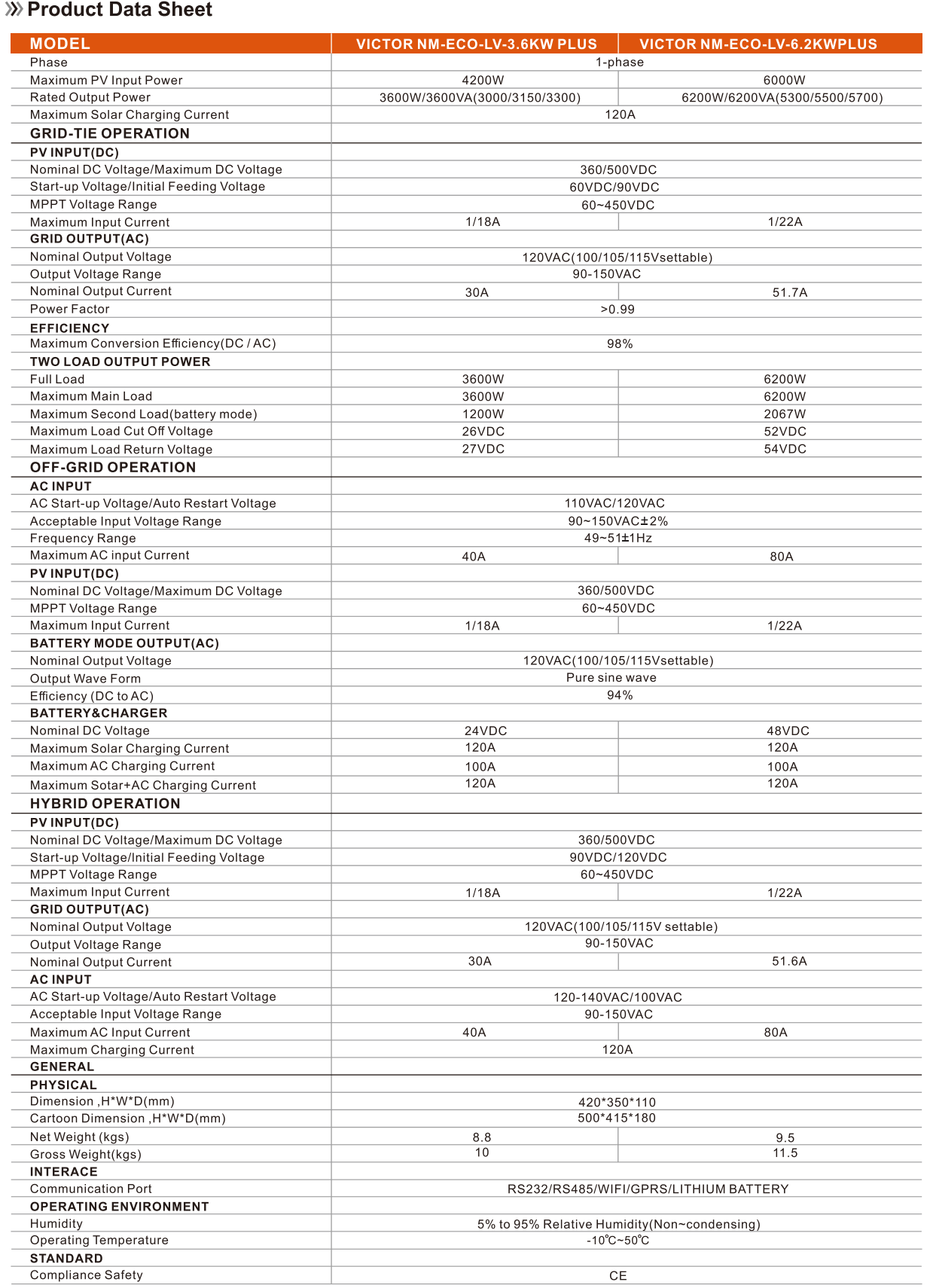
Detailed product data sheet for the Sumry Hybrid Solar Inverter, including specifications for both 3.6KW and 6.2KW models.
7.1 General Specifications
| Attribute | Value |
|---|---|
| Model Number | ECO LV 3.6KW |
| Continous Power | 3.6KW |
| Output Power | 1 - 200 KW |
| Output Current | 20A |
| AC Output Voltage | 110VAC -50Hz/60Hz |
| Output Frequency | 50/60HZ |
| Wave Form | Pure Sine Wave |
| Battery Voltage | 24VDC |
| Max Charge Current for Battery | 60A |
| Max Charge Current for Solar | 80A |
| Control Type | MPPT |
| Support Battery Type | Lithium battery, LiFePo4 |
| Communication Interface | RS232 |
| Size | 50*41.5*18cm |
| Weight | 10KG |
| Certification | CE |
7.2 Line Mode Specifications
| Parameter | 3.6KW | 6.2KW |
|---|---|---|
| Input Voltage Waveform | Sinusoidal (utility or generator) | |
| Nominal Input Voltage | 100Vac | 100Vac |
| Low Loss Voltage (UPS) | 90Vac±5V | 90Vac±5V |
| Low Loss Voltage (Appliances) | 90Vac±5V | 90Vac±5V |
| High Loss Voltage | 145Vac±5V | 145Vac±5V |
| Max AC Input Voltage | 150Vac | 150Vac |
| Nominal Input Frequency | 50Hz / 60Hz (Auto detection) | |
| Efficiency (Line Mode) | >95% (Rated R load, battery full charged) | |
| Transfer Time (UPS) | 10ms typical | 10ms typical |
| Transfer Time (Appliances) | 20ms typical | 20ms typical |
7.3 Inverter Mode Specifications
| Parameter | 3.6KW | 6.2KW |
|---|---|---|
| Rated Output Power | 3.6KW | 6.2KW |
| Output Voltage Waveform | Pure Sine Wave | |
| Output Voltage Regulation | 100/105/110/115/120Vac±5% | |
| Peak Efficiency | 93% | 93% |
| Overload Protection | 3s@≥150%; 5s@101%~150% load | |
| Surge Capacity | 2* rated power for 5 seconds | |
| Nominal DC Input Voltage | 24Vdc | 48Vdc |
| Cold Start Voltage | 23.0Vdc | 46.0Vdc |
| No Load Power Consumption | 45W | 50W |
7.4 Charge Mode Specifications
| Parameter | 3.6KW | 6.2KW |
|---|---|---|
| Charging Algorithm | 3-Step | |
| AC Charging Current (Max) | 80Amp (@VI/P=100 Vac) | |
| Max. PV Array Power | 4200W | 6500W |
| Nominal PV Voltage | 240Vdc | 360Vdc |
| PV Array MPPT Voltage Range | 60Vdc~500Vdc | |
| Max Charging Current (AC charger plus solar charger) | 120Amp | 120Amp |
7.5 Grid-Tie Operation Specifications
| Parameter | 3.6KW | 6.2KW |
|---|---|---|
| Nominal Output Voltage | 100/105/110/115/120VAC | |
| Feed-in Grid Voltage Range | 90~150VAC | |
| Feed-in Grid Frequency Range | 49~51±1Hz/59~61±1Hz | |
| Nominal Output Current | 30A | 51.7A |
| Maximum Conversion Efficiency (DC/AC) | 97% | |
8. User Tips
- Grid-Tie Functionality: This inverter is capable of returning power to the grid. Ensure your system is configured correctly for grid-tie operation if you intend to feed excess power back.
- WiFi and App Monitoring: The inverter supports WiFi and app monitoring for iOS and Android devices. To use this feature, you will need to purchase a separate WiFi module and connect it to the RS232 communication port. Download the official app and follow the 'Wi-Fi Plug Quick Installation Guideline' for setup.
- Circuit Breaker Sizing: For the 3.6KW model, use a 2P100A circuit breaker between the battery and inverter, a 2P20A for PV input, a 2P50A for utility input, and a 2P30A for the inverter output. Always ensure correct sizing for safety.
- Battery Compatibility: The inverter is compatible with a wide range of battery types, including Lithium, LiFePO4, Gel, Lead-acid, and AGM batteries.
9. Frequently Asked Questions (FAQ)
- Q: Does this inverter return power to the grid?
- A: Yes, this inverter is designed with grid-tie capabilities and can return power to the grid when configured appropriately.
- Q: Is WiFi and app monitoring included?
- A: The inverter supports WiFi and app monitoring for iOS and Android. However, the WiFi module is an optional accessory and needs to be purchased separately. Once acquired, it connects via the RS232 port for remote monitoring and parameter adjustments.
10. Warranty and Support
For detailed information regarding warranty terms, technical support, or service, please refer to the official user manual PDF. You can view the full user manual here.