
Introduction
This manual provides essential information for the installation, operation, and maintenance of your 60V 50A DC Brushless Controller Dual Motor system. Designed for electric scooters and e-bikes, these controllers offer high strength and durability. Please read this manual thoroughly before installation and use to ensure safe and optimal performance.

Figure 1: Overview of the Dual 60V 50A DC Brushless Controllers.
Specifications
| Feature | Detail |
|---|---|
| Type | 60V 50A DC Brushless Controller Dual Motor |
| Voltage | 60V |
| Current | 50A |
| Color | Silver |
| Material | Metal |
| Dimensions (L x W x H) | Approximately 150mm x 84mm x 43mm |
| Origin | Mainland China |
| Customization | No |
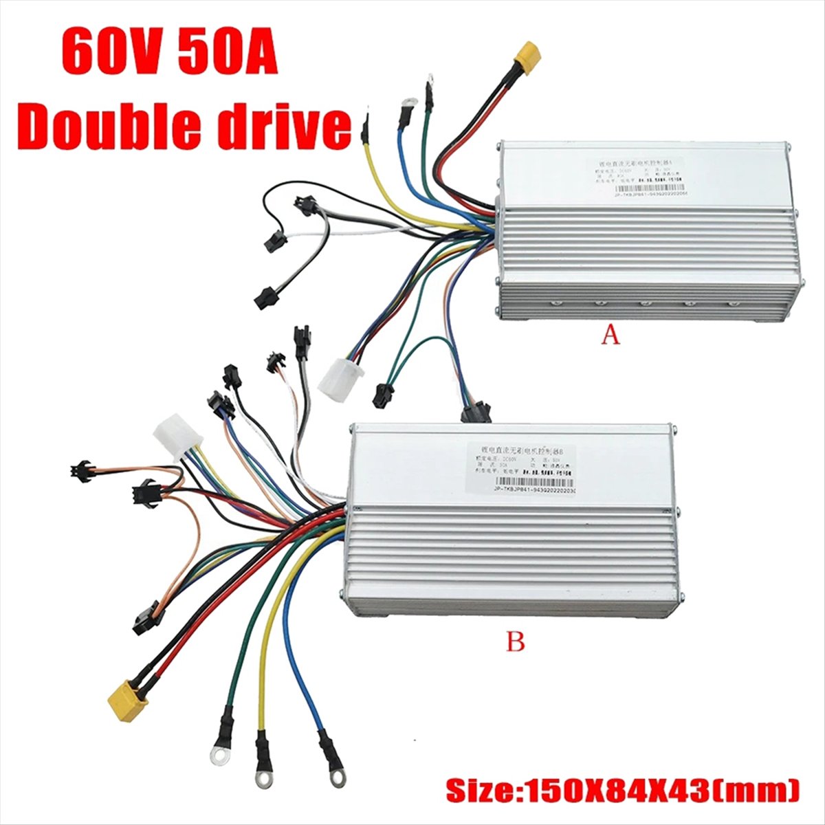
Figure 2: Controller A with dimensions.
Installation and Wiring
The installation of brushless motor controllers requires careful attention to wiring to ensure proper function and safety. It is highly recommended that installation be performed by a qualified technician or an experienced individual. Always disconnect the battery before beginning any wiring work.
General Wiring Connections:
The controllers feature multiple connectors for various functions. While specific wiring diagrams vary by scooter/e-bike model, the general types of connections include:
- Power Input: Connects to the battery (typically thick red for positive, thick black for negative).
- Motor Phase Wires: Connects to the motor's three phase wires (typically thick yellow, green, blue).
- Hall Sensor Wires: Connects to the motor's Hall sensors (smaller wires, usually red, black, yellow, green, blue).
- Throttle/Accelerator: Connects to the throttle input.
- Brake Levers: Connects to the brake cut-off switches.
- Ignition/Key Switch: For turning the system on/off.
- Display/Meter: For connecting to the vehicle's display unit.
- Self-Learning/Intelligent Identification Wires: Often two wires that, when connected briefly, allow the controller to learn motor parameters.
- Cruise Control: If applicable.
- Anti-Theft/Alarm: If applicable.
WARNING: Incorrect wiring can damage the controllers, motor, battery, or cause injury. Always consult the specific wiring diagram for your electric scooter or e-bike model. If no diagram is available, seek professional assistance.
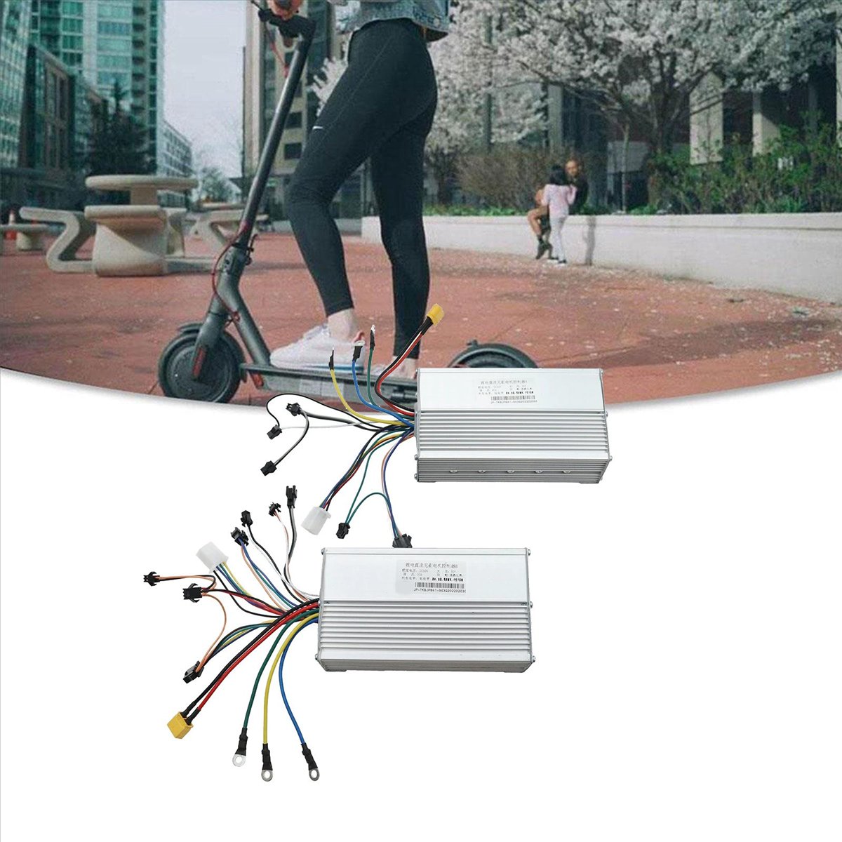
Figure 3: Example of a single controller's wiring harness.
Installation Steps (General):
- Ensure the vehicle's power is off and the battery is disconnected.
- Mount the controllers securely in a location that is protected from water and excessive vibration, allowing for adequate airflow for cooling.
- Carefully connect the main power wires (battery to controller).
- Connect the motor phase wires and Hall sensor wires to the respective motor.
- Connect the throttle, brake, ignition, and any other auxiliary wires according to your vehicle's wiring diagram.
- For dual motor setups, ensure both controllers are wired correctly and synchronized if required by your vehicle's design.
- Once all connections are made, double-check every wire for correct polarity and secure fitment.
- Reconnect the battery and test the system in a safe environment.
Operation
Once correctly installed, the brushless controllers manage the power delivery to your electric scooter or e-bike motors based on throttle input and other sensor data.
- Power On: Turn on the vehicle's ignition or power switch. The controllers will initialize.
- Throttle Control: Gently apply the throttle to accelerate. The controllers will regulate motor speed and power.
- Braking: Engaging the brake levers will typically cut power to the motors, and some systems may also engage regenerative braking through the controllers.
- Dual Motor Operation: For dual motor setups, both controllers work in tandem to power the front and rear motors (or two motors on the same axle), providing enhanced power and torque.

Figure 4: Controllers in use on an electric scooter.
Maintenance
These controllers are designed for durability and require minimal maintenance. However, regular checks can prolong their lifespan and ensure reliable operation.
- Keep Clean: Periodically clean the exterior of the controllers to prevent dust and debris buildup, which can hinder heat dissipation.
- Check Connections: Ensure all wiring connections remain tight and free from corrosion. Loose connections can lead to intermittent power, overheating, or damage.
- Inspect for Damage: Regularly inspect the controller housing and wires for any signs of physical damage, cracks, or frayed insulation.
- Avoid Water Exposure: While robust, avoid submerging the controllers in water or exposing them to heavy rain for extended periods.
- Heat Management: Ensure the controllers are not covered or obstructed, allowing for proper airflow to dissipate heat during operation.
Troubleshooting
If you encounter issues with your brushless controllers, consider the following common problems and solutions:
| Problem | Possible Cause | Solution |
|---|---|---|
| Motor does not spin / No power | Loose power connection, discharged battery, faulty ignition switch, faulty throttle. | Check all power connections. Ensure battery is charged. Test ignition and throttle. |
| Motor spins erratically or with noise | Incorrect Hall sensor wiring, damaged Hall sensors, incorrect phase wire connection. | Verify Hall sensor and phase wire connections. Perform self-learning function if available. |
| Controller overheats | Insufficient ventilation, excessive load, short circuit in motor or wiring. | Ensure proper airflow around controller. Reduce load. Check motor and wiring for shorts. |
| Brakes do not cut power | Brake lever switch faulty or disconnected. | Check brake lever switch wiring and functionality. |
If troubleshooting steps do not resolve the issue, consult a professional technician.
User Tips
- Dual Controller Synchronization: For dual motor setups, ensure both controllers are properly synchronized according to your vehicle's specifications. Some systems require specific wiring or a "self-learning" process to ensure both motors operate harmoniously.
- Wiring Diagrams: Always refer to the specific wiring diagram provided by your scooter or e-bike manufacturer. Generic diagrams may not match your exact model.
- Professional Installation: Given the complexity of electrical systems, consider professional installation to avoid potential damage or safety hazards.
Warranty and Support
For warranty information or technical support, please contact the seller or manufacturer directly. Keep your purchase receipt as proof of purchase.