
1. Introduction
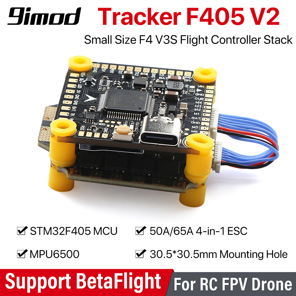
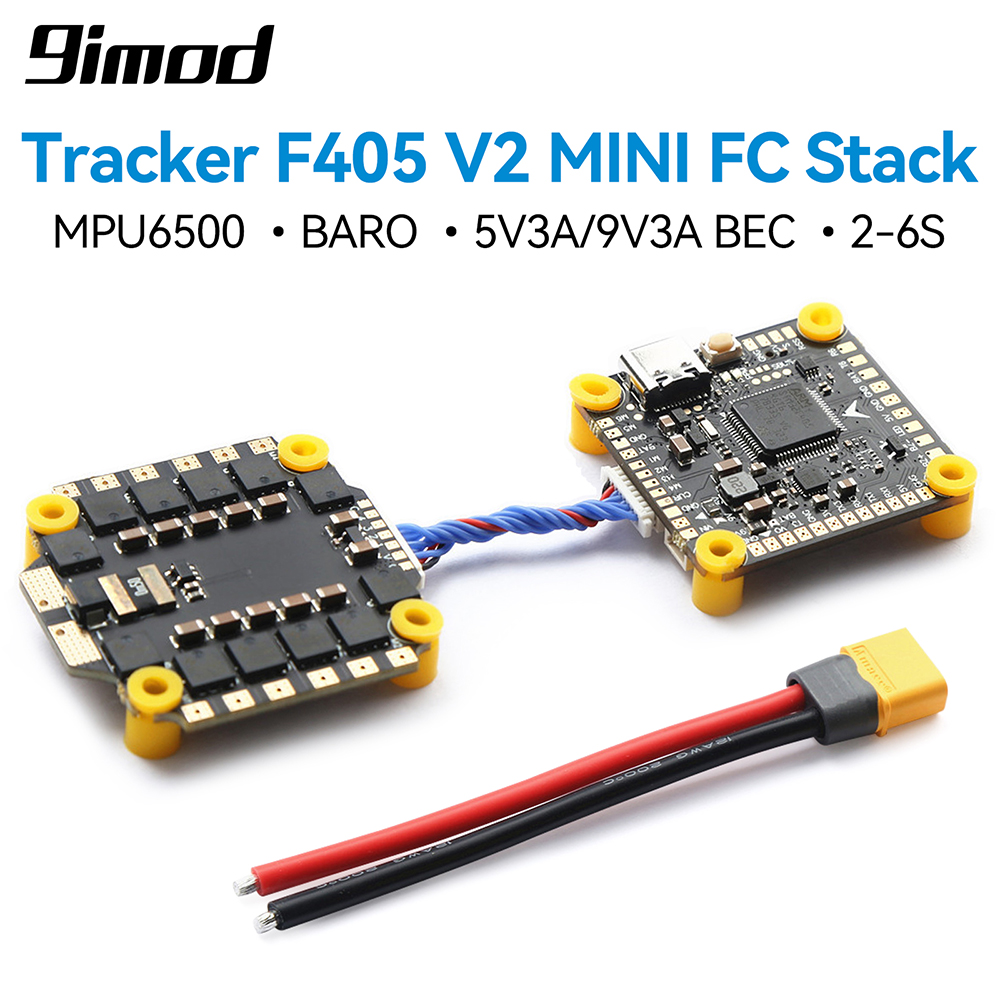
The 9IMOD Tracker F405 V2 Flight Control Stack is a high-performance integrated solution designed for RC FPV Drones and Quadcopters. It combines an F405 V2 Flight Controller (FC) with either a 50A or 65A 4-in-1 Electronic Speed Controller (ESC), offering robust control and power delivery for a smooth flight experience. This manual provides essential information for the proper setup, operation, and maintenance of your flight control stack.
2. Product Overview
2.1 Key Features
- Built with the powerful STM32F405 MCU for advanced processing.
- Supports Betaflight for comprehensive parameter tuning and configuration.
- Integrated MPU6500 gyroscope for precise flight stabilization.
- Includes a barometer (BMP280) for accurate altitude holding.
- High-current 50A or 65A 4-in-1 ESC options for 2-6S LiPo batteries.
- Supports DShot150-300-600/Multishot/Oneshot/PMW drive signals.
- Features a MicroSD card slot for black box flight logging.
- Integrated BEC (5V3A/9V3A) for powering peripherals.
- Compact design with 30.5x30.5mm mounting holes (3mm after shock absorber ball installation).
2.2 Components
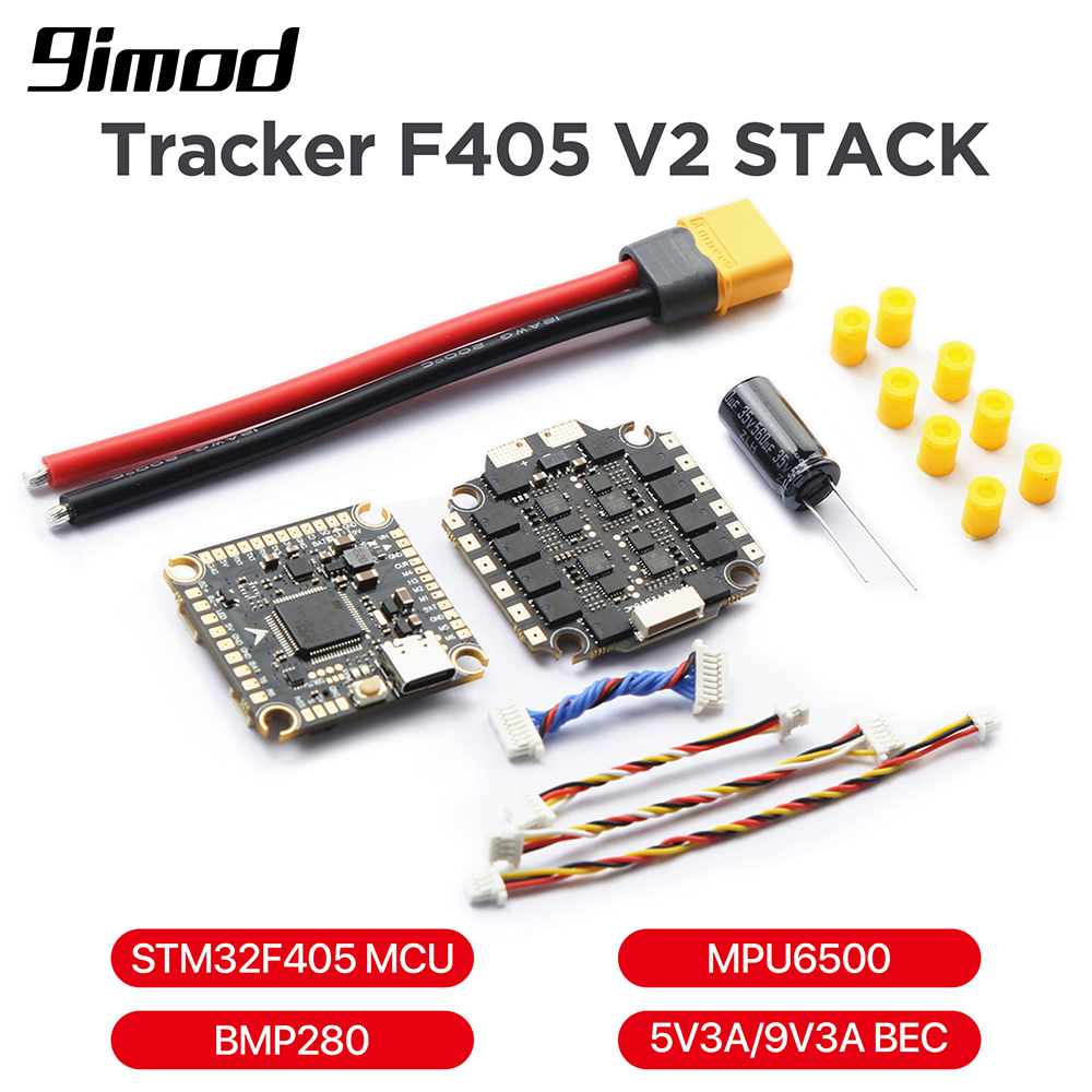
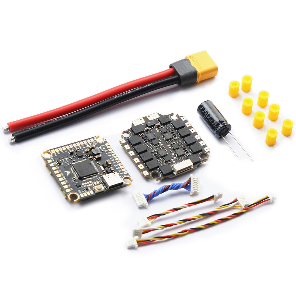
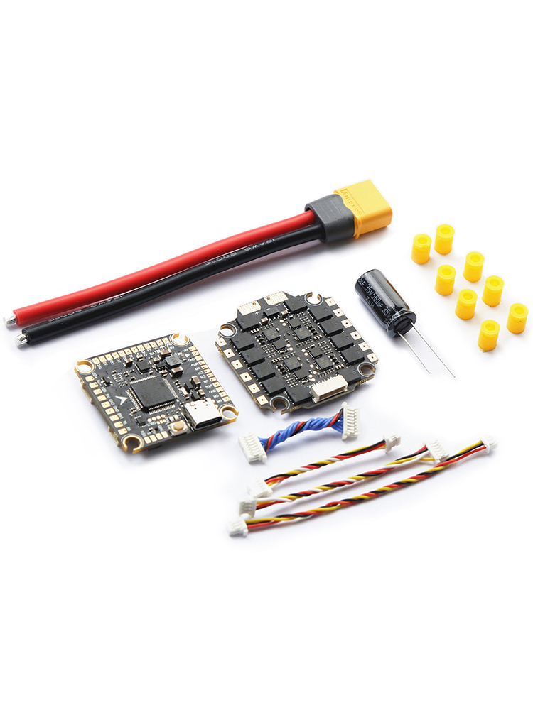
The 9IMOD Tracker F405 V2 Flight Control Stack typically includes:
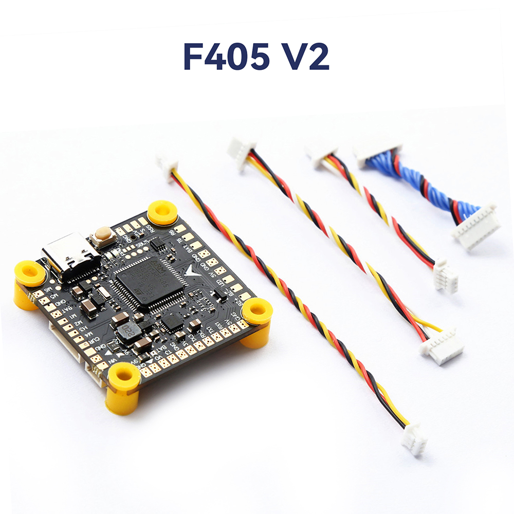
- 1 x 9IMOD Tracker F405 V2 Flight Controller
- 1 x 9IMOD Tracker 50A V2 or 65A V2 4-in-1 ESC (depending on selection)
- Connection cables (e.g., ribbon cable for FC-ESC connection, receiver wires)
- Capacitor
- Mounting hardware (e.g., shock absorber balls)

3. Specifications
3.1 F405 V2 Flight Controller
| Feature | Specification |
|---|---|
| Size | 36x36mm |
| Weight | 13g |
| Installation Hole | 30.5x30.5mm |
| Microcontroller | STM32 F405 |
| Gyroscope | MPU6500 |
| Barometer | BMP280 |
| BEC Output | 5V3A / 9V3A |
| OSD | Drag and drop configured through Betaflight |
| Black Box | MicroSD card support |
| Receiver Support | ELRS/CRSF/SBUS/IBUS PPM/Spektrum DSMX, etc. |
| Video Filter | Car video filter (5V to VTX and camera only) |
| Firmware Support | Betaflight (INAV not supported) |
| Suitable Models | 5 to 15 inches traversing aircraft/drones |
3.2 50A V2 4-in-1 ESC
| Feature | Specification |
|---|---|
| Size | 41 x 39 x 5mm |
| Aperture | 30.5 x 30.5mm (3mm after shock absorber ball) |
| Weight | 15g |
| Firmware | BLHELI-S |
| Input Voltage | LIPO 2-6S |
| Continuous Current | 50A |
| Maximum Current | 55A (10 seconds) |
| Processor | EF8BB21 |
| Drive Signal Support | DShot150-300-600/Multishot/Oneshot/PMW |
| Current Sensor | Supports |
3.3 65A V2 4-in-1 ESC
| Feature | Specification |
|---|---|
| Size | 41 x 39 x 5mm |
| Aperture | 30.5 x 30.5mm (3mm after shock absorber ball) |
| Weight | 15g |
| Firmware | BLHELI-S |
| Input Voltage | LIPO 2-6S |
| Continuous Current | 65A |
| Maximum Current | 70A (10 seconds) |
| Processor | EF8BB21 |
| Drive Signal Support | DShot150-300-600/Multishot/Oneshot/PMW |
| Current Sensor | Supports |
4. Setup
4.1 Mounting the Stack
- Ensure your drone frame has 30.5x30.5mm mounting holes.
- Install the provided shock absorber balls into the mounting holes of your frame.
- Carefully place the ESC onto the shock absorber balls, ensuring correct orientation.
- Connect the FC to the ESC using the provided ribbon cable, aligning the pins correctly.
- Place the FC onto the ESC, securing it with the remaining shock absorber balls or nuts if applicable.
4.2 Wiring Connections
Refer to the pinout diagrams on the FC and ESC for specific connections. Common connections include:
- Battery (LiPo): Connect the main battery lead to the ESC's power pads (red for positive, black for negative). Ensure the included capacitor is soldered to the main battery pads on the ESC to filter power spikes.
- Motors: Solder motor wires to the corresponding motor pads on the ESC (M1-M4).
- Receiver: Connect your receiver (ELRS/CRSF/SBUS/IBUS PPM/Spektrum DSMX) to the appropriate UART on the FC.
- VTX (Video Transmitter): Connect VTX power and video signal to the FC. The FC provides a 5V filtered output for VTX and camera.
- Camera: Connect camera power and video input to the FC.
- GPS/Other Peripherals: Connect to available UARTs or I2C pads as needed.
Warning: Always double-check all wiring connections for correct polarity and pin assignment before applying power to avoid damage to components.

4.3 Betaflight Configuration
The F405 V2 Flight Controller is designed to be configured using Betaflight firmware. You will need to:
- Download and install the latest Betaflight Configurator software on your computer.
- Connect the FC to your computer via a USB-C cable.
- Flash the appropriate Betaflight firmware for the F405 target.
- Configure your receiver, motors, ESC protocols (DShot recommended), OSD, and other settings within the Betaflight Configurator.
- Perform sensor calibration (accelerometer, gyroscope, barometer).
- Test motor direction and responsiveness.
Note: The F405 flight controller only supports Betaflight software and does not support INAV firmware.
5. Operating Instructions
Once your 9IMOD Tracker F405 V2 Flight Control Stack is correctly installed and configured with Betaflight, follow these general operating guidelines:
- Pre-Flight Check: Always perform a visual inspection of your drone before each flight. Check for loose wires, damaged propellers, and secure battery connection.
- Arming/Disarming: Arm and disarm your drone using the configured switch on your remote controller. Ensure you are in a safe area before arming.
- Flight Modes: Utilize the flight modes configured in Betaflight (e.g., Acro, Angle, Horizon, GPS Rescue if applicable) according to your flying skill and environment.
- Monitoring: Use the OSD (On-Screen Display) to monitor critical flight data such as battery voltage, current draw, flight mode, and RSSI.
- Black Box Logging: If you have installed a MicroSD card, flight data will be logged automatically. This data can be invaluable for tuning and troubleshooting.
6. Maintenance
Regular maintenance helps ensure the longevity and reliable performance of your flight control stack:
- Visual Inspection: Periodically check for any signs of physical damage, such as cracked solder joints, burnt components, or frayed wires.
- Cleaning: Gently clean the FC and ESC with a soft brush or compressed air to remove dust, dirt, or debris. Avoid using liquids directly on the electronics.
- Firmware Updates: Keep your Betaflight firmware and BLHELI-S ESC firmware updated to benefit from performance improvements and bug fixes. Always back up your configuration before updating.
- Component Check: Ensure all connectors are securely seated and that mounting hardware remains tight.
- Capacitor Health: Inspect the main power capacitor for any bulging or leakage, which could indicate failure.
7. Troubleshooting
If you encounter issues with your flight control stack, consider the following common troubleshooting steps:
- No Power/No Lights: Check battery connection, main power lead, and ensure no short circuits. Verify USB connection for FC.
- Motors Not Spinning/Erratic Behavior:
- Check motor wiring and solder joints.
- Verify ESC firmware and settings in Betaflight Configurator (e.g., DShot protocol, motor direction).
- Ensure motors are correctly assigned in Betaflight.
- No Receiver Input:
- Check receiver wiring to the FC (signal, ground, power).
- Verify UART configuration in Betaflight for your receiver type.
- Ensure receiver is bound to your radio transmitter.
- OSD Not Displaying Correctly: Check OSD settings in Betaflight Configurator. Ensure video signal from camera to FC and FC to VTX is correct.
- Unstable Flight:
- Recalibrate accelerometer.
- Check for vibrations (loose components, unbalanced propellers).
- Review PID tuning settings in Betaflight.
- FC Not Connecting to Betaflight Configurator:
- Ensure correct USB drivers are installed.
- Try a different USB cable or port.
- Enter DFU mode if flashing firmware.
8. User Tips
- Start with Defaults: When first setting up, use Betaflight's recommended default settings for your frame size and then make small adjustments.
- Backup Your Configuration: Always save a backup of your Betaflight configuration (CLI dump) after successful setup and before making major changes or firmware updates.
- Heat Shrink/Conformal Coating: Consider applying heat shrink to exposed solder pads on the ESC or a conformal coating to the entire stack for added protection against moisture and debris, especially for outdoor flying.
- Proper Soldering: Ensure all solder joints are clean, shiny, and strong to prevent intermittent connections or failures during flight.
- Power Distribution: Use the BEC outputs on the FC for powering low-current peripherals like receivers and cameras, reserving direct battery power for high-current components like VTX (if it requires more than BEC can provide).
9. Support
For further assistance, technical support, or specific inquiries regarding your 9IMOD Tracker F405 V2 Flight Control Stack, please contact the seller or manufacturer directly. Provide your product model and a detailed description of the issue for efficient support.