
1. Introduction
This manual provides detailed instructions for the installation, operation, and maintenance of your MakeSkyBlue 40A V123 MPPT Solar Charge Controller. This controller is designed for 12V, 24V, and 48V lead-acid battery systems, offering efficient and safe charging from solar panels.
Important Safety Notice: Please read this manual thoroughly before installation and operation to ensure proper use and prevent damage or injury.
2. Safety Information
- Ensure all connections are correct and secure before powering on the system.
- Always disconnect PV modules before setting up or adjusting the solar charge controller.
- Use appropriate DC circuit breakers and cables as specified to prevent overcurrent and short circuits.
- Do not exceed the maximum PV Open Circuit Voltage (Voc) specified for your battery system. Exceeding 180V Voc can permanently damage the controller.
- Only use the provided screws for mounting to avoid damaging the internal PCB. Apply proper torque when tightening screws.
- The controller is designed for indoor use.
- Refer to the troubleshooting section for error codes and solutions.

3. Package Contents
Verify that all items are included in your package:
- 1 x MPPT Solar Charge Controller (Model: 40A-V123)
- 1 x User Manual
- 1 x Set of Mounting Brackets and Screws (4 mounting brackets, 4 screws for controller casing)
4. Specifications
| Feature | Specification |
|---|---|
| Model No. | 40A-V123 |
| Charging Technology | MPPT / Maximum Power Point Tracking |
| Charging Mode | 3-stage: Constant current (MPPT), Constant voltage (Absorption voltage), Floating charge |
| System Type | DC12V/24V/48V (Automatic Recognition) |
| Automatic Select Voltage Range | 12V system (DC9V-DC15V), 24V system (DC18V-DC29V), 48V system (DC40V~DC60V) |
| Soft Start Time | ≤1S |
| Dynamic Response and Recovery Time | 100µs |
| Max Efficiency | ≥98.2% |
| PV Utilization | ≥99% |
| Self Consumption | ≤1.2W |
| Input Specification | |
| Voc Range of PV | 12V system (DC20V~DC80V), 24V system (DC37V~DC105V), 48V system (DC72V~DC160V) (Optimal efficiency when PV Voc is 1.5 to 2 times battery voltage) |
| Maximum PV Module Open Circuit Voltage | For 12V battery: 80V, For 24V battery: 105V, For 48V battery: 160V (Never exceed max PV Voc. Voc > 180V will burn the controller.) |
| Maximum Nominal PV Power | 12V system (≤480W), 24V system (≤960W), 48V system (≤1700W) |
| Output Specification | |
| Selectable Battery Type | Vented / Sealed / Gel / NiCd battery (User-defined voltage, selectable as Lead-acid or Lithium in settings) |
| Absorption Charging Voltage | Refer to Manual Setting (D02): 12V to 17V (for 12V battery), 24V to 34V (for 24V battery), 48V to 68V (for 48V battery) |
| Floating Charging Voltage | Refer to Manual Setting (D01): 12V to 17V (for 12V battery), 24V to 34V (for 24V battery), 48V to 68V (for 48V battery) |
| Overcharging Protection Voltage | 12V system (15V), 24V system (30V), 48V system (60V) |
| Rated Output Current | 40A |
| Output Voltage Ripple-peak | 100mV |
| Output Voltage Accuracy | ≤±1% |
| Protection Function | |
| Temperature Protection | 75 °C / 167℉ |
| Fan-on Temperature | >45 °C / 113℉ |
| Fan-off Temperature | <40 °C / 104℉ |
| PV Reverse Polarity Protection | Yes (When Voc<100V only) |
| PV Over-voltage Protection | Yes (When Voc>180V, the controller will be burnt.) |
| Battery Overcharge Current Protection | Yes |
| Battery Overcharge Voltage Protection | Yes |
| Battery Low Voltage Protection | Yes |
| Enclosure | |
| Acoustic Noise | ≤40dB |
| Cooling Way | Forced air cooling |
| Components | Industrial grade |
| Size (L*W*H) | 21.5 x 11.5 x 5 cm / 8.46 x 4.52 x 1.96 in |
| Net Weight | 1.3kg / 2.86lb |
| Gross Weight | 1.4kg / 3.08lb |
| Safety Certifications | EN 62109-1, EN 60730-1, EN IEC 61000-6-3, EN IEC 61000-6-1 |
| Protection Category | IP21 |
| Environmental Condition | Indoor |
| Operating Temperature | -20℃ ~ +55℃ / -4℉ ~ +131℉ |
| Storage Temperature | -40℃ ~ +75℃ / -40℉ ~ +167℉ |


5. Installation
5.1. General System Overview
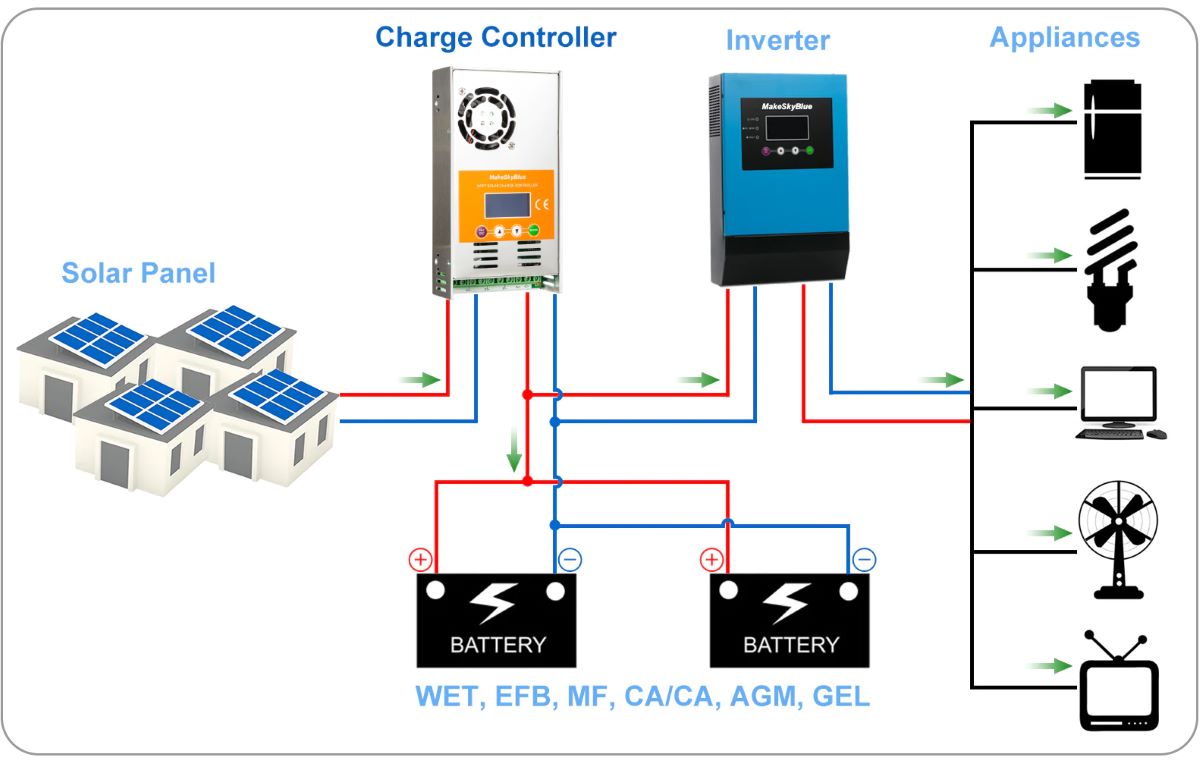
5.2. Choosing Solar Panels
When selecting solar panels, ensure the PV array's Open Circuit Voltage (Voc) and Nominal PV Power are within the controller's limits. Refer to the table below for guidance:
| Parameter | 40A-V123 |
|---|---|
| Nominal PV Power for 12V Battery | ≤480W |
| Nominal PV Power for 24V Battery | ≤960W |
| Nominal PV Power for 48V Battery | ≤1700W |
| PV Open Circuit Voltage for 12V Battery | 20V~80V |
| PV Open Circuit Voltage for 24V Battery | 37V~100V |
| PV Open Circuit Voltage for 48V Battery | 72V~160V |
| Maximum PV Array Open Circuit Voltage | For 12V battery: 80V For 24V battery: 100V For 48V battery: 160V |
5.3. Selecting DC Circuit Breaker and Cables
Use flexible multi-stranded copper cable for both battery and PV connections. Refer to the table below for recommended specifications:
| Component | 40A-V123 |
|---|---|
| Pure copper cables | 4pcs 6mm² / 9 AWG |
| Connection (PV) | One cable to one PV+ Another cable to one PV- |
| Connection (Battery) | One cable to one BAT+ Another cable to one BAT- |
| DC Circuit Breaker | 2pcs 63A |
5.4. Connection Steps
Caution: Always ensure DC circuit breakers are OFF before making any connections.
- Connect the Battery:
- Ensure the DC circuit breaker for the battery is OFF.
- Install the circuit breaker between the controller and the battery (above 12V).
- Connect the battery cables to the controller.
- Check battery polarity carefully.
- Turn the battery DC circuit breaker ON. The controller's LCD should display current and version.
- Set the controller parameters (refer to Section 6.3 Manual Setting).
- Turn the battery DC circuit breaker OFF after setting parameters.
- Connect GND: Connect a cable to Battery negative from controller screw.
- Connect DC Loads (if needed): Connect your DC loads to the appropriate terminals on the controller.
- Connect the PV:
- Ensure the DC circuit breaker for the PV is OFF.
- Install the circuit breaker between the controller and the PV modules.
- Connect the PV cables to the controller.
- Check PV polarity carefully.
- Turn the PV DC circuit breaker ON.
- Final Power On: Turn ON the DC circuit breaker between the controller and batteries, then turn ON the DC circuit breaker between the controller and PV modules.
- Verification: The controller LCD should display the parameters correctly.
- WiFi CloudBox (Optional): If you have a WiFi CloudBox (excluded for V123 model), connect it now.

6. Operation
6.1. Initial Display and LCD Data
Upon startup, the LCD will show an initial page indicating the current and version. The LCD provides various data points and working modes:
LCD Data
| No. | Description |
|---|---|
| 1 | PV voltage / Output power |
| 2 | Battery voltage / Charging current |
| 3 | Working mode / Error code / Temperature |
| 4 | ACC Power Generation |
Working Modes
| Code | Description |
|---|---|
| 3.0 | Night mode, no charging |
| 4.0 | MPPT mode |
| 7.0 | Absorption mode |
| 8.0 | Floating mode |
6.2. Smart App Control (Optional)
The controller supports smart app control for real-time monitoring and adjustment. If you have a WiFi CloudBox (not included with V123), you can use the SmartLife app.
App Download:
Search for "SmartLife" in the Google Play Store (Android) or App Store (iOS).

After downloading, log in or register, then add your device. Ensure your phone and device are on the same Wi-Fi network for configuration.
6.3. Manual Setting
Caution: Disconnect the PV modules before setting up the solar charge controller manually.
To access settings, press the "PRG" button. Use "UP" and "DOWN" buttons to navigate and "ENTER" to confirm.
- D00: Load Working Time (Default: 24-hour). The load output is for DC loads < 5 Amps; output voltage matches battery voltage.
- D01: Floating Charge Voltage (Set between 12V to 17V for 12V systems, 24V to 34V for 24V systems, 48V to 68V for 48V systems).
- D02: Absorption Voltage (Constant Voltage) (Set between 12V to 17V for 12V systems, 24V to 34V for 24V systems, 48V to 68V for 48V systems).
- D03: Battery Discharge Protection Voltage.
- D04: Battery Type:
- 00: Lead-acid battery
- 01: Lithium battery
- D05: Clear WiFi Password (for WiFi version).
- D06: Battery Voltage Calibration: Use this to calibrate the battery voltage if your meter shows a different reading than the controller. Exercise caution when using this function.
Reminder: The controller operates effectively with default settings for lead-acid batteries. After connecting all cables and setting up, reboot the controller to ensure settings are applied.
7. Troubleshooting
Refer to the table below for common issues and their solutions:
| Code | Description | How to Solve |
|---|---|---|
| 18 | Input PV voltage is low | Increase the PV voltage. |
| 60 | Over-temperature protection | The fan will work automatically for temperature reduction. |
| 63 | Battery voltage is high | Battery high voltage protection with automatic recovery. |
| 65 | Battery voltage is low | Battery over-discharge protection with automatic recovery. |
| 71 | Input PV voltage is high | Decrease the PV voltage/power to be within the correct Voc (open-circuit voltage) range. |
| 73 | Over-charging current | Decrease the PV voltage/power to be within the correct Voc (open-circuit voltage) range. |
| 74 | Output load is short | Disconnect the load, then press and hold the "ENT" button for over 5 seconds. |
8. Maintenance
To ensure optimal performance and longevity of your solar charge controller, consider the following maintenance tips:
- Regularly inspect all wiring connections for tightness and corrosion.
- Keep the controller clean and free from dust and debris. Ensure ventilation openings are not blocked.
- Periodically check the battery terminals for corrosion and clean if necessary.
- Monitor the LCD display for any error codes or unusual readings.
- Ensure the environment remains within the specified operating temperature range.
9. User Tips
While no specific user reviews or Q&A were provided, here are some general tips for maximizing your solar charge controller's performance:
- Always size your solar panels and batteries appropriately for your energy needs to prevent undercharging or overstressing the system.
- Consider using a battery monitor to keep track of your battery's state of charge and health.
- For optimal MPPT performance, ensure your PV array's open-circuit voltage (Voc) is significantly higher than your battery voltage (ideally 1.5 to 2 times).
- If using the SmartLife app, ensure your Wi-Fi network is stable for reliable monitoring.
10. Support and Contact Information
For technical support or inquiries, please contact MakeSkyBlue (Shenzhen) Technology Co., LTD:
- Address: 702b, Bldg. C6, Hengfeng Industry Zone, Hezhou, Baoan, Shenzhen Guangdong 518101 China
- Telephone: +86 755 27595076
- Website: www.makeskyblue.com
- Email: sales@makeskyblue.com
A digital version of this user manual is available for download: User Manual (PDF)