
1. Introduction
This manual provides comprehensive instructions for the installation, operation, and maintenance of your OBO Hands Door Access Control System Kit. This system is designed to provide secure access management for various door types, including wooden, iron, and glass doors, utilizing RFID cards, passwords, or a combination of both.
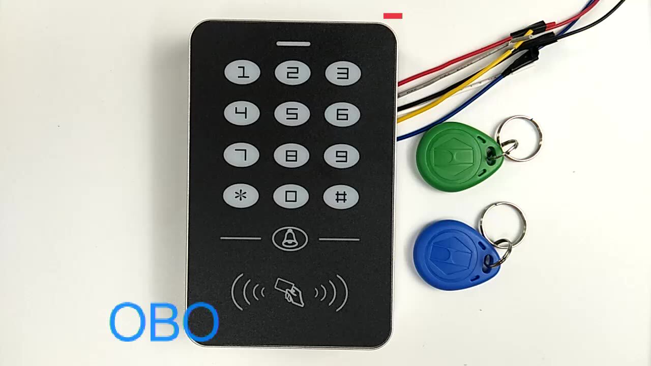
The kit includes an access controller, power supply, door exit button, RFID keyfobs, and a choice of electric locks and brackets tailored to your specific door requirements.

2. Safety Information
- Read all instructions carefully before installation and use.
- Ensure all power is disconnected before performing any wiring or installation procedures to prevent electric shock.
- Installation should be performed by qualified personnel if you are unsure about electrical wiring.
- Do not expose the access controller directly to heavy rain; it is surface waterproof but not fully submersible (not IP65 rated).
- Keep away from fire and extreme temperatures.
- Use only the specified DC12V power supply.
3. Package Contents
Your OBO Hands Door Access Control System Kit typically includes the following components. Specific lock types and brackets vary depending on the kit purchased.
- Access Control Keypad (A1 model)
- Power Supply Control Unit (AC90V-260V Input, DC12V 3A Output)
- Door Exit Button
- RFID Keyfobs (10 pieces, mixed colors by default)
- Selected Electric Lock (e.g., Electric Strike Lock, Electric Drop Bolt Lock, 180KG Electric Magnetic Lock, Embedded 180KG Electric Magnetic Lock)
- Optional Brackets (e.g., U bracket, L bracket, ZL bracket) depending on the lock and door type.
4. Specifications
4.1 Access Controller (Model A1)
- User Capacity: 1000 users
- Card Reading Type: EM card (125KHz)
- Card Reading Distance: 1-5 CM
- Identification Methods: Card, Password, Card + Password
- Programming Password: 123456 (Default)
- Unlocking Time: 5 seconds
- Door Open Input: One-way button input
- Doorbell Output: One-way wired doorbell output
- Compatibility: Can be connected to automatic doors or gates
- Working Voltage: DC 12V ± 10%
- Working Power Supply: <100mA
- Working Temperature: 0 °C ~ 60 °C
- Dimensions: 113mm (L) x 70mm (W) x 20mm (H)
- Security Mode: Fail Safe
- Certification: CE


4.2 Power Supply Control Unit
- Material: Steel
- Output Power: 36W
- Durability Test: 500,000 times
- Input Frequency: 50-60Hz
- Input Voltage: 110-260VAC
- Output Voltage: DC12V/3A
- Working Temperature: -20 °C to +65 °C
- Time Delay: 0-15 seconds (adjustable)
- Relative Humidity: 0%-90%
- Dimensions: 100mm (L) x 65mm (W) x 32mm (H)


4.3 Door Exit Button
- Material: Hard Plastic
- Maximum Power Rating: 36V DC 3A-5A output
- Mode Support: NC Mode (Fail Safe) & NO Mode (Fail Secure)
- Dimensions: 86mm (L) x 86mm (W)
4.4 RFID Keyfobs
- Frequency: 125KHz
- Detection Range: 0-10cm
- Feature: Each card is pre-programmed with a unique identity number.
4.5 Electric Locks (General Dimensions)

5. Installation and Setup
The installation process varies slightly depending on the type of electric lock and door you have. Please identify your kit and door type before proceeding.
5.1 General Wiring Diagram
The following diagram illustrates the general wiring connections between the Access Controller, Power Supply, Exit Button, and Electric Locks. Ensure all connections are secure and follow local electrical codes.

5.2 Access Controller Mounting
Mount the access controller at a convenient height near the door. The ABS flame-retardant casing is integrally formed. After installation, a layer of glass glue can be applied to the back cover for enhanced surface waterproof effect (not IP65 waterproof, avoid direct rain exposure).

5.3 Kit-Specific Installation Guides
Kit3: Electric Strike Lock
Suitable for: Wooden doors, metal doors. Convenient and beautiful, no additional bracket needed.
- Lock Type: Electric Strike Lock
- Working Voltage: 12V ± 10%
- Current: 200mA - 450mA
- Holding Force: 500kg
- Working Temperature: -30 to +60 Celsius Degree
- Operating Humidity: 0~90% (non-condensing)
- Feature: Fail secure (NO) or Fail safe (NC). Default is NC type (Locked when power on, unlocked when power off). If NO type is desired (Locked when power off, unlocked when power on), please ensure you have the correct model.
- Material: Stainless steel
- Size: 150 x 28 × 34mm (L / W / H)

Kit4: Electric Drop Bolt Lock
Suitable for: Wooden, metal, and stainless steel doors. No additional bracket needed.
- Lock Type: Electric Drop Bolt Lock
- Working Voltage: 12V
- Time Delay: 0s, 3s, 6s (adjustable)
- Working Current: Start state 1.2A; Persistent state 120mA
- Coil Type: Continuous working
- Security Type: Electric power lock, unlock
- Lock Core: Diameter 12.5MM stainless core, extending length 15MM
- Locking Mode: Magnetic induction
- Unlock Mode: Fail Safe (Locked when power on, unlocked when power off)
- Dimensions: 150mm (L) x 34mm (W) x 28mm (H)

Kit5: 180KG Electric Magnetic Lock
Suitable for: Wooden, metal, and glass frame doors. No additional bracket needed.
- Lock Type: 180KG Electric Magnetic Lock
- Material: Aluminum alloy shell + iron plate
- Holding Force: 180KG/350lbs
- Working Voltage: DC12V
- Working Current: 380-430mA
- Humidity: 0 to 95%
- Working Temperature: -10 to 55 Celsius degree
- Working Mode: Power-on to lock, power-off to unlock
- Waterproof: Yes, can be installed outside.

Kit6: 180KG Magnetic Lock with U Bracket
Suitable for: Frameless glass doors. Requires a U bracket.
- Lock Type: 180KG Magnetic Lock
- Bracket: U bracket
- U Bracket Size: 130mm (L) x 33mm (W) x 26mm (H)

Kit7: 180KG Magnetic Lock with L Bracket
Suitable for: Wooden, metal doors. Requires an L bracket if the door is flat or the gap between the door and frame is less than 3cm when viewed from indoors.
- Lock Type: 180KG Magnetic Lock
- Bracket: L bracket
- L Bracket Size: 170mm (L) x 34mm (W) x 25mm (H)

Kit8: 180KG Magnetic Lock with ZL Bracket
Suitable for: Wooden, metal, glass doors. Requires a ZL bracket if the door opens inwards.
- Lock Type: 180KG Magnetic Lock
- Bracket: ZL bracket
- L Bracket Size: 170mm (L) x 34mm (W) x 25mm (H)
- Z Bracket Size: 138mm (L) x 45mm (W) x 45mm (H)

Kit9: Embedded 180KG Electric Magnetic Lock
Suitable for: Wooden, metal, and glass frame doors. No additional bracket needed.
- Lock Type: Embedded 180KG Electric Magnetic Lock
- Lock Size: 192mm (L) x 33mm (W) x 20mm (H)
- Armature Plate Size: 139mm (L) x 32mm (W) x 11mm (H)
- Holding Force: 180kg (350Lbs)
- Input Voltage: 12VDC
- Current: 12V/120mA

6. Operating Instructions
6.1 Default Settings
- Default Programming Password: 123456
- Default Unlock Time: 5 seconds
6.2 Programming the Access Controller
The access controller supports adding and deleting user cards and passwords. The default programming password is 123456.


Entering Programming Mode:
- Press
*(Star key). - Enter the 6-digit Programming Password (default: 123456).
- Press
#(Hash key). The indicator light will change, indicating you are in programming mode.
Adding User Cards:
- Enter Programming Mode.
- Press
1(Add User Card). - Present the RFID card to the card reading area. The controller will beep to confirm.
- To add more cards, repeat step 3.
- Press
#to exit adding cards mode, or*to exit programming mode.
Adding User Passwords:
- Enter Programming Mode.
- Press
2(Add User Password). - Enter a 4-digit to 6-digit password.
- Press
#to confirm. The controller will beep. - To add more passwords, repeat steps 3-4.
- Press
#to exit adding passwords mode, or*to exit programming mode.
Deleting User Cards/Passwords:
- Enter Programming Mode.
- Press
3(Delete User). - To delete by card: Present the RFID card to the card reading area.
- To delete by password: Enter the user password and press
#. - The controller will beep to confirm deletion.
- Press
#to exit deleting mode, or*to exit programming mode.
Changing Programming Password:
- Enter Programming Mode.
- Press
8(Change Admin Password). - Enter the new 6-digit programming password.
- Press
#to confirm. The controller will beep. - Press
*to exit programming mode.
6.3 Unlocking the Door
- Using RFID Card: Present a registered RFID card to the card reading area on the access controller.
- Using Password: Enter your registered password on the keypad and press
#. - Using Card + Password: Present your registered RFID card, then enter your password and press
#. This method provides higher security. - Using Exit Button: Press the internal exit button to open the door from the inside.
7. Maintenance
- Cleaning: Wipe the access controller and other components with a soft, dry cloth. Avoid abrasive cleaners or solvents.
- Power Supply: Ensure the power supply unit is kept in a well-ventilated area and free from dust accumulation.
- Wiring: Periodically check all wiring connections for any signs of wear, corrosion, or looseness.
- Card Management: Regularly review and update user cards and passwords, especially if there are changes in personnel.
8. Troubleshooting
| Problem | Possible Cause | Solution |
|---|---|---|
| System not powering on. | No power to the power supply unit; faulty wiring; power supply failure. | Check main power connection. Verify all wiring connections to the power supply. Test power supply output. |
| Door does not unlock with valid card/password. | Card/password not properly registered; lock mechanism jammed; faulty wiring to the lock; incorrect lock type (NC/NO). | Ensure card/password is correctly programmed. Check for obstructions in the lock. Verify wiring to the electric lock. Confirm the lock's fail-safe/fail-secure mode matches your setup. |
| Exit button not working. | Faulty wiring to the exit button; faulty exit button. | Check wiring connections for the exit button. Test the exit button for continuity. |
| Doorbell not ringing. | Doorbell not connected; faulty doorbell; wiring issue. | Ensure wired doorbell is correctly connected to the access controller's doorbell output. Check doorbell functionality. |
| Access controller indicator lights not functioning. | Power issue; controller malfunction. | Verify power supply. If power is present, the controller may be faulty and require replacement. |
9. User Tips
- Professional Installation: If you are not experienced with electrical wiring or door hardware installation, consider hiring a professional to ensure correct and safe setup.
- Wiring Clarity: Pay close attention to the wiring diagrams. Double-check all connections before applying power.
- Power Outage: For Fail Safe locks (unlocked when power off), consider a backup power supply if continuous security during power outages is critical. For Fail Secure locks (locked when power off), ensure there's an alternative entry method during power outages.
- Programming: Take your time when programming cards and passwords. Confirm each step with the controller's beeps or indicator lights.
- Documentation: Keep this manual and any additional notes on your specific setup in a safe place for future reference.
10. Frequently Asked Questions (FAQ)
- Q: What type of product is this?
- A: This is an OBO Hands Door Access Control System Kit, designed for secure entry management using RFID cards and passwords.
- Q: How do I set up a code and add RFID cards?
- A: Please refer to Section 6.2 "Programming the Access Controller" for detailed instructions on adding user cards and passwords, and changing the programming password.
- Q: Where can I find the connection plan/wiring diagram?
- A: A general wiring diagram is provided in Section 5.1. Specific installation diagrams for different lock kits are available in Section 5.3.
- Q: What happens if there is a power outage? Will I be able to get into the room?
- A: The behavior during a power outage depends on the type of electric lock installed:
- Fail Safe Locks (e.g., Electric Strike Lock (NC type), Electric Drop Bolt Lock, Magnetic Locks): These locks unlock when power is lost. You will be able to enter the room.
- Fail Secure Locks (e.g., Electric Strike Lock (NO type)): These locks remain locked when power is lost. You will need an alternative method of entry (e.g., a mechanical key if the lock supports it, or a backup power supply).
- Please check the specifications of your specific electric lock to understand its behavior during a power failure.
11. Warranty and Support
For warranty information and technical support, please refer to the seller's policies or contact OBO Hands customer service directly. Keep your purchase receipt as proof of purchase.