1. Introduction
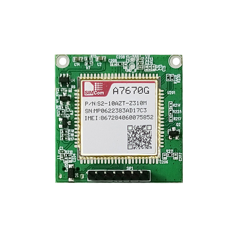
The SIMCOM A7670G-LABE is a versatile LTE CAT1 4G global-band core board designed for a wide range of IoT and M2M applications. This development board provides robust cellular communication capabilities, making it suitable for projects requiring reliable data transmission across various network bands. It features a highly integrated design with support for multiple frequency bands, wide voltage input, and comprehensive data resources for developers.

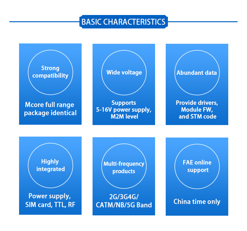
2. Key Features
The A7670G-LABE core board offers a range of features to facilitate development and deployment:
- Strong Compatibility: Utilizes an Mcore full-range package, ensuring identical form factor and broad compatibility.
- Wide Voltage Support: Operates with a 5-16V DC power supply, suitable for various M2M level applications.
- Abundant Data Resources: Provides drivers, module firmware (FW), and STM code to aid in development.
- Highly Integrated Design: Incorporates power supply, SIM card interface, TTL, and RF components on a single board.
- Multi-frequency Support: Compatible with 2G, 3G, 4G, CATM, NB, and 5G bands for global connectivity.
- Online Technical Support: FAE (Field Application Engineer) online support is available during China time.
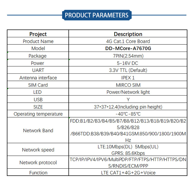
3. Specifications
The following table details the technical specifications of the SIMCOM A7670G-LABE Core Board:
| Project | Description |
|---|---|
| Product Name | 4G Cat.1 Core Board |
| Model | DD-MCore-A7670G |
| Package | 7PIN (2.54mm) |
| Power | 5-16V DC |
| UART | 3.3V TTL (Default) |
| Antenna interface | IPEX 1 |
| SIM Card | MIRCO SIM |
| LED | Power/Network light |
| USB | Yes |
| SIZE | 37*37*12.4mm (Including pin height) |
| Operating temperature | -40°C - 85°C |
| Network Band | FDD:B1/B2/B3/B4/B5/B7/B8/B12/B13/B18/B19/B20/B2/B66 TDD:B38/B39/B40/B41 GSM:850/900/1800/1900MHz |
| Network speed | LTE:10Mbps(DL) 5Mbps(UL), GPRS: 85.6Kbps |
| Network protocol | TCP/IP/IPV4/IPV6/MultiPDP/FTP/FTPS/HTTP/HTTPS/DNS/RNDIS/ECM/PPP |
| Function | LTE CAT1+4G+2G+Voice |
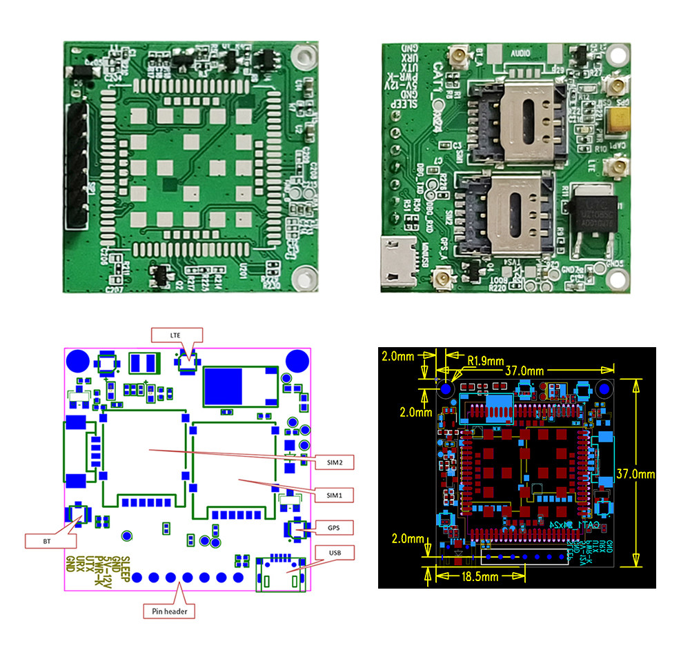
4. Setup Instructions
- Prepare Components: Ensure you have the A7670G-LABE core board, a compatible antenna (IPEX 1 interface), a Micro SIM card, and a 5-16V DC power supply.
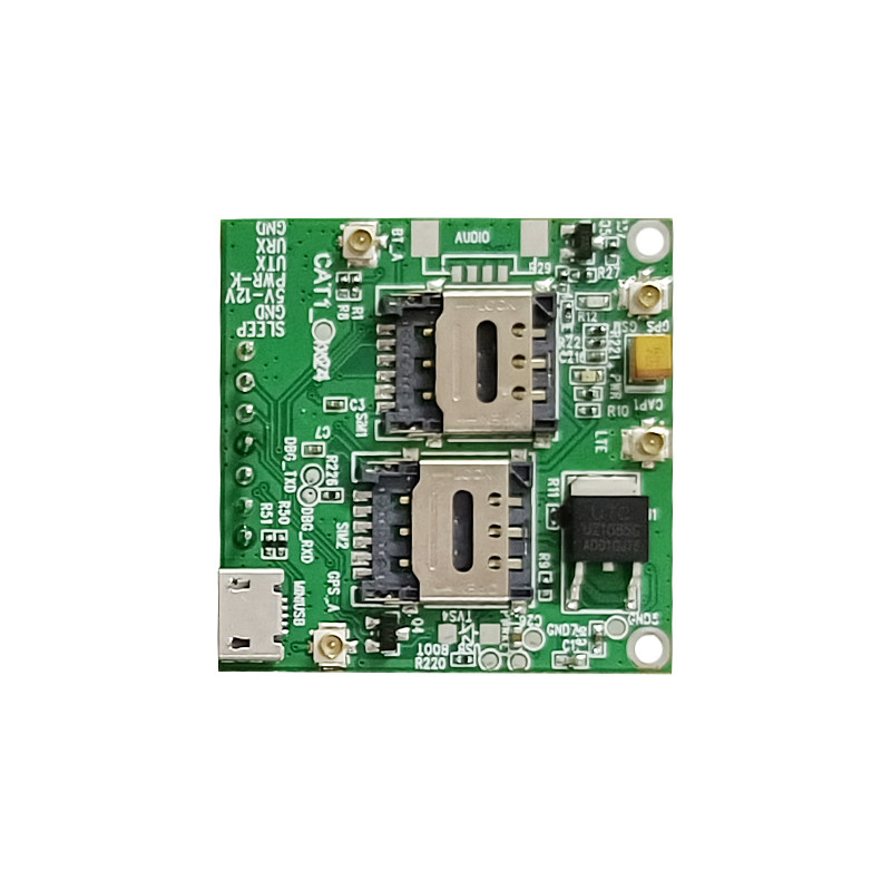
- Insert SIM Card: Carefully insert the Micro SIM card into the designated SIM card slot(s) on the board. Ensure it is correctly oriented and securely seated.
- Connect Antenna: Attach the cellular antenna to the IPEX 1 connector on the board. For optimal performance, ensure the antenna is positioned away from other electronic components.
- Power Connection: Connect the 5-16V DC power supply to the appropriate power input pins (VBUS, GND). Observe polarity to prevent damage.
- Data Connection (Optional): For initial configuration or data communication, connect the board to your development environment via the USB port or UART interface (3.3V TTL).
- Power On: Apply power to the board. The Power LED should illuminate, and the Network LED will indicate network registration status (blinking for searching, solid for registered).

5. Operating Instructions
The A7670G-LABE module is primarily controlled via AT commands sent over the UART or USB interface. Refer to the official SIMCOM AT Command Set documentation for a complete list of commands and their usage.
5.1 Basic Operation
- Power On/Off: The module powers on automatically when voltage is applied. Software commands or a dedicated power key pin can be used for controlled shutdown.
- Network Registration: After powering on, the module will attempt to register with the cellular network. Monitor the Network LED or use AT commands (e.g.,
AT+CREG?) to check registration status. - Data Connection: Establish a data connection using appropriate AT commands for PDP context activation and network connection (e.g.,
AT+CGACT,AT+CIPSTART). - Voice Calls: The module supports voice functionality. Use AT commands for making and receiving calls (e.g.,
ATDfor dialing,ATAfor answering).
5.2 AT Command Examples (Conceptual)
AT: Checks if the module is responding. Expected response:OK.AT+CSQ: Checks signal quality. Expected response:+CSQ: <rssi>,<ber>.AT+COPS?: Queries the currently registered operator.AT+CIMI: Retrieves the International Mobile Subscriber Identity (IMSI).
For detailed command syntax and responses, consult the SIMCOM A7670G AT Command Manual.
6. Applications
The SIMCOM A7670G-LABE core board is suitable for a wide array of applications across various industries due to its robust connectivity and compact size:
6.1 Intelligent Agriculture
- Agricultural irrigation systems
- Agricultural greenhouse monitoring
- Animal husbandry and aquaculture management
6.2 Sharing Economy
- Tracking and control for shared toy cars
- Smart massage chairs
- Connected vending machines
- IoT-enabled toy machines and coffee machines
6.3 Wisdom Energy
- Smart charging pile management and monitoring
6.4 Smart Industry
- Remote control systems
- Data monitoring for industrial equipment
- Centralized monitor consoles
7. Maintenance
To ensure the longevity and optimal performance of your SIMCOM A7670G-LABE Core Board, follow these maintenance guidelines:
- Environmental Conditions: Operate the board within the specified operating temperature range (-40°C to 85°C). Avoid exposure to extreme temperatures, high humidity, dust, and corrosive environments.
- Handling: Handle the board with care, preferably by the edges, to avoid damaging components or connectors. Use anti-static precautions when handling to prevent electrostatic discharge (ESD).
- Cleaning: If cleaning is necessary, use a soft, dry, anti-static cloth. Do not use liquid cleaners or solvents.
- Firmware Updates: Regularly check the official SIMCOM website for firmware updates. Keeping the firmware up-to-date can improve performance, add features, and resolve bugs.
- Power Supply: Always use a stable and regulated 5-16V DC power supply. Incorrect voltage or unstable power can damage the module.
8. Troubleshooting
If you encounter issues with your A7670G-LABE core board, consider the following troubleshooting steps:
- No Power:
- Check power supply connections and ensure correct voltage (5-16V DC) and polarity.
- Verify the power supply is functional.
- Ensure the power LED on the board is illuminated.
- No Network Registration:
- Check if the SIM card is correctly inserted and activated.
- Ensure the antenna is securely connected to the IPEX 1 port.
- Verify that you are in an area with cellular network coverage.
- Use the
AT+CSQcommand to check signal strength. Low signal strength can prevent registration. - Use the
AT+CREG?command to check network registration status.
- Communication Issues (UART/USB):
- Verify correct wiring for UART (TX, RX, GND) and baud rate settings.
- Ensure USB drivers are correctly installed on your computer if using the USB interface.
- Check if the correct COM port is selected in your terminal software.
- Module Not Responding to AT Commands:
- Ensure the module is powered on and the power LED is stable.
- Check the serial connection and baud rate.
- Try sending a simple
ATcommand to verify basic communication.
9. User Tips
- Start with Basic AT Commands: Before diving into complex applications, familiarize yourself with basic AT commands to ensure the module is functioning correctly and communicating with the network.
- Refer to Documentation: Always consult the official SIMCOM A7670G documentation, including the hardware design guide and AT command set, for detailed technical information.
- Power Supply Stability: Use a high-quality, stable power supply to prevent unexpected behavior or damage to the module, especially during data transmission peaks.
- Antenna Placement: Proper antenna placement is crucial for good signal reception. Avoid placing the antenna near metal objects or other RF-emitting devices.
- Development Environment: Utilize a reliable serial terminal program for sending AT commands and monitoring responses.
10. Warranty and Support
For technical support, documentation, and warranty information regarding your SIMCOM A7670G-LABE Core Board, please refer to the official SIMCOM website or contact your distributor. Emaxgroup Cellular Wireless communication Store provides technical assistance and resources for this product.
It is recommended to keep your purchase records for any warranty claims.
11. Product Roadmap Overview
The following video provides an overview of the SIMCOM Core Board Product Roadmap, showcasing various function boards and their features across different series.


