
1. Introduction
This manual provides essential information for the safe and effective use of your Flipsky 75100 or 75100 Pro Electronic Speed Controller (ESC). These high-performance ESCs are designed for electric skateboards, scooters, ebikes, and other similar electric vehicles, offering precise motor control based on VESC technology. Please read this manual thoroughly before installation and operation to ensure optimal performance and safety.

2. Specifications
The Flipsky 75100 and 75100 Pro ESCs feature robust design and advanced capabilities for demanding applications.
| Feature | Specification |
|---|---|
| Model (75100) Dimensions | L103mm * W58mm * H18.5mm + 5.9mm (USB Type) |
| Model (75100 Pro) Dimensions | L103mm * W58mm * H27.7mm |
| Voltage Range | 14-84V (4-20S) |
| Continuous Current | 100A |
| Burst Current | 120A |
| BEC Output | 5V @ 1.5A |
| Motor Control Modes | BLDC Square Wave, FOC Sine Wave |
| Firmware | Latest (firmware update supported) |
| Max ERPM | 150,000 |
| Control Interface Ports | USB, CAN, UART |
| Supported Sensors | ABI, HALL, AS5047, AS5048A |
| Input Set Support | PPM, ADC, NRF, UART |
| Wire Size (75100) | 12AWG |
| Wire Size (75100 Pro) | 10AWG |
| Programmable | Yes |
| Regenerative Capacity | Yes |
| Material | Metal (Aluminum PCB and case for heat dissipation) |

3. Safety Information
WARNING: Incorrect configuration or handling can damage the ESC and connected components, and may pose a safety risk.
- Always ensure the ESC is powered off before making any connections or disconnections.
- Avoid pulling directly on wires when unplugging connectors; always press the release mechanism if present, or gently pull the connector housing to prevent damage to wires and connectors.
- Ensure all connections are secure and properly insulated to prevent short circuits.
- Operate the ESC within its specified voltage and current limits.
- Keep the ESC away from water, moisture, and extreme temperatures.
- Do not attempt to modify the ESC hardware.
4. Setup & Installation
Proper installation is crucial for the performance and longevity of your ESC. Follow these general guidelines:
- Mounting: Securely mount the ESC in a location that allows for adequate airflow and protection from physical damage and environmental elements.
- Motor Connection: Connect the three motor phase wires to the corresponding outputs on the ESC.
- Battery Connection: Connect the battery's positive and negative terminals to the ESC's main power input. Ensure correct polarity.
- Sensor Connections: If using sensored motors, connect the motor's sensor cable to the HALL port on the ESC.
- Control Input: Connect your chosen control input (e.g., PPM receiver, UART device) to the appropriate port on the ESC.
- Peripheral Connections: Connect any other peripherals (e.g., CAN bus devices, USB for configuration) as needed.
Important: Refer to the detailed wiring diagrams in the next section for specific connection points.
5. Wiring Diagrams
These diagrams illustrate the various connection points on your Flipsky ESC. Ensure all connections are made correctly before powering on the device.
5.1. Flipsky 75100 with Aluminum Case Wiring Diagram

5.2. Flipsky 75100 Pro with Aluminum Case Wiring Diagram

6. Configuration (Software)
The Flipsky ESCs are configured using the VESC_TOOL software. It is critical to follow the recommended settings to prevent damage.
- Firmware: It is strongly recommended to keep the factory-shipped firmware (e.g., firmware 5.2). Upgrading to newer firmware versions may potentially damage the ESC if not done correctly or if specific settings are not adjusted.
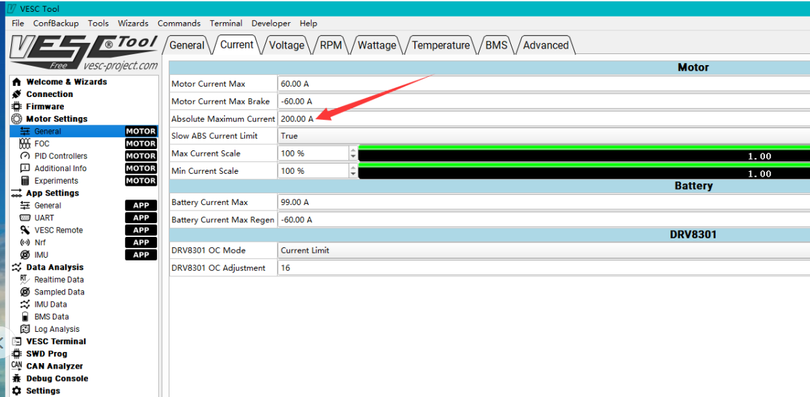
- Absolute Maximum Current: When configuring, ensure the "Absolute Maximum Current" setting is limited to below 250A. Exceeding this limit can lead to ESC failure.
- Phase Filtering (Firmware 5.3+): For firmware versions 5.3 and above (using VESC_TOOL 3.01 or newer), phase filtering is NOT available for Flipsky ESC75100 and 75200. You MUST turn off the phase filter function and set it to "false" in VESC_TOOL. Failing to do so will result in ESC damage. Do not restore default parameters when using the wizard interface.
For detailed configuration guides and troubleshooting related to VESC_TOOL, please consult official Flipsky resources or community forums. External video and blog resources may also be available for specific setup procedures.
7. Operation
Once the ESC is correctly installed and configured, you can begin operation. The ESC translates control signals from your input device (e.g., remote control, throttle) into motor commands, regulating speed and direction.
- Always perform initial tests at low speeds in a safe, open area.
- Monitor the ESC and motor for unusual heat, noise, or behavior during operation.
- Ensure your battery is adequately charged for your intended use.
- Avoid sudden, extreme changes in throttle input, especially at high speeds, to prevent excessive current draw and potential damage.
8. Troubleshooting
This section addresses common issues you might encounter.
- ESC not powering on / No motor response:
- Check all power connections from the battery to the ESC for secure contact and correct polarity.
- Verify that the battery is charged.
- Inspect control input connections (PPM, UART, etc.) and ensure the remote/controller is powered on and paired.
- Check for any visible damage to the ESC or wiring.
- Motor stutters or runs erratically:
- Ensure motor phase wires are correctly connected and not loose.
- If using a sensored motor, check the sensor cable connection.
- Re-run motor detection in VESC_TOOL.
- Verify that phase filtering is correctly disabled if using firmware 5.3 or higher.
- ESC gets excessively hot:
- Ensure the ESC has adequate airflow and is not enclosed in a tight space.
- Check motor current limits in VESC_TOOL; ensure "Absolute Maximum Current" is below 250A.
- Verify that the motor is not overloaded or experiencing excessive resistance.
- Consider reducing continuous current settings if operating in high-stress conditions.
- ESC damaged after firmware update:
- As noted in the Configuration section, new firmware upgrades can be risky. It is recommended to stick with the factory firmware (e.g., 5.2) unless absolutely necessary and performed with extreme caution, following all specific instructions for the new firmware version.
- Ensure phase filtering is disabled for firmware 5.3+ to prevent damage.
9. User Tips
- Included Accessories: Users often inquire about included connection wires. Please check the product packaging or description at the time of purchase to confirm what accessories are supplied with your specific ESC model.
- Connector Care: Always handle connectors with care. When disconnecting, gently press any release tabs or pull on the connector housing itself, rather than the wires, to prevent wire breakage or damage to the connector pins.
- Configuration Backup: Before making significant changes in VESC_TOOL, it's good practice to save your current configuration settings. This allows you to revert to a known working state if issues arise.
10. Maintenance
Regular maintenance helps ensure the longevity and reliable operation of your Flipsky ESC.
- Cleaning: Keep the ESC clean and free from dust, dirt, and debris. Use a soft, dry brush or compressed air to remove any buildup.
- Inspection: Periodically inspect all wires and connectors for signs of wear, fraying, or corrosion. Replace any damaged components immediately.
- Environmental Protection: While the aluminum case provides some protection, avoid exposing the ESC to harsh environments, excessive moisture, or direct impacts.
- Thermal Management: Ensure the ESC's heatsink fins are clear of obstructions to allow for efficient heat dissipation.
11. Warranty & Support
For warranty information, technical support, or service inquiries, please contact the manufacturer (Flipsky) or your point of purchase. Keep your proof of purchase for warranty claims.
Always refer to the official Flipsky website or documentation for the most up-to-date information and support resources.