1. Introduction
The Honeywell DC1020 Series Digital Temperature Controller is a versatile and reliable device designed for precise temperature control in various industrial and commercial applications. This manual provides essential information for the safe and efficient installation, operation, and maintenance of your DC1020 controller.
2. Safety Information
Please read and understand all safety instructions before installing or operating the DC1020 controller. Failure to follow these instructions may result in equipment damage, personal injury, or death.
- Electrical Hazard: Ensure all power is disconnected before wiring or performing maintenance. Only qualified personnel should perform electrical connections.
- Proper Grounding: Always ensure the device is properly grounded to prevent electrical shock.
- Environmental Conditions: Do not expose the controller to excessive moisture, dust, corrosive gases, or extreme temperatures beyond its specified operating range.
- Intended Use: Use the controller only for its intended purpose as a temperature control device.
3. Package Contents
Upon opening the package, verify that all components are present and undamaged:
- Honeywell DC1020 Digital Temperature Controller
- User Manual (this document)
- Mounting hardware (if applicable)

4. Installation and Wiring
4.1 Physical Installation
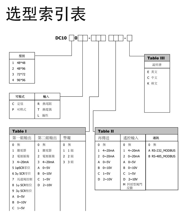
The DC1020 controller is designed for panel mounting. Ensure adequate space for ventilation and access to wiring terminals. Refer to the product's dimensions for precise panel cutout requirements (e.g., 48x48mm, 48x96mm, 72x72mm, or 96x96mm depending on the specific model variant).
4.2 Wiring Connections
WARNING: Disconnect all power before making any wiring connections.
The wiring configuration varies based on the specific model (e.g., input type, output type). Below are common wiring diagrams for different DC1020 variants. Always refer to the diagram printed on your specific unit for accurate connections.
4.2.1 Wiring for DC1020CR-701000-E (PT3 Input, Motor Valve Output)
| Terminal No. | Description |
|---|---|
| 1, 2 | AC Power Supply (L, N) 85-265V |
| 3, 4, 5 | Alarm 1 Output (NO, NC, COM) |
| 7, 8 | Motor Valve Control (CLOSE, OPEN) |
| 9, 10 | Common for Motor Valve |
| 17, 18, 19, 20 | Input for PT3 Sensor (0-850°C) |
4.2.2 Wiring for DC1020CR-301000-E (PT1 Input, 4-20mA Output)

| Terminal No. | Description |
|---|---|
| 1, 2 | AC Power Supply (L, N) 85-265V |
| 3, 4, 5 | Alarm 1 Output (NO, NC, COM) |
| 8, 9, 10 | Output 1 (e.g., Relay or 4-20mA) |
| 17, 18, 19, 20 | Input for PT1 Sensor (-199.9-850.0°C) or 4-20mA |
5. Operating Instructions
5.1 Front Panel Overview

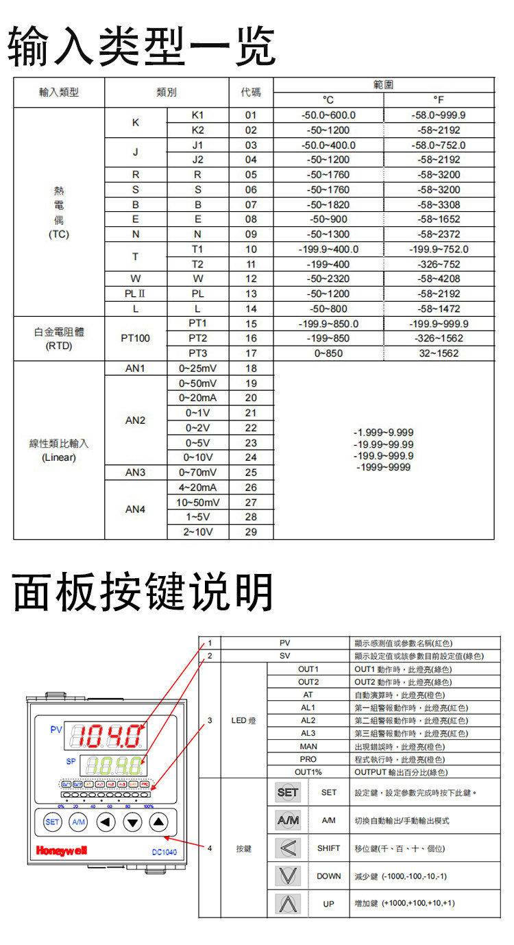
| Element | Description |
|---|---|
| PV Display (Red) | Shows the current Process Value (measured temperature). |
| SP Display (Green) | Shows the Set Point (desired temperature). |
| OUT1/OUT2 LEDs | Indicate output status (e.g., heating/cooling active). |
| AT LED | Indicates Auto-Tuning status. |
| AL1/AL2/AL3 LEDs | Indicate alarm status. |
| MAN LED | Indicates Manual control mode. |
| PRO LED | Indicates Program mode. |
| Output Bar Graph | Visual representation of output power (0-100%). |
| A/M Button | Switches between Automatic and Manual control modes. |
| SET Button | Enters parameter setting mode and confirms selections. |
| Up (▲) Button | Increases parameter value or navigates to the next parameter. |
| Down (▼) Button | Decreases parameter value or navigates to the previous parameter. |
| Left/Shift (◀) Button | Shifts the cursor during parameter editing or views different parameters. |
5.2 Basic Operation
- Power On: After correct wiring, apply power to the controller. The PV and SP displays will light up.
- Setting the Set Point (SP):
- Press the SET button briefly. The SP display will flash.
- Use the ▲ and ▼ buttons to adjust the desired set point.
- Use the ◀ button to shift the digit for faster adjustment.
- Press SET again to confirm and exit SP setting mode.
- Auto/Manual Mode: Press the A/M button to toggle between Automatic (PID control) and Manual control modes. In Manual mode, you can directly adjust the output percentage.
- Parameter Settings: To access advanced parameters (e.g., PID constants, alarm settings, input type), press and hold the SET button for several seconds until the parameter menu appears. Navigate using ▲ and ▼, and adjust values using ▲, ▼, and ◀. Press SET to confirm each parameter.
6. Technical Specifications
Specifications may vary slightly depending on the exact model variant (e.g., DC1020CR-701000-E, DC1020CT-101000-E). Always refer to the label on your specific unit.
| Feature | Specification |
|---|---|
| Model Number | DC1020 Series |
| Supply Voltage | AC 85-265V |
| Frequency | 50/60 Hz |
| Power Consumption | Max 8VA (varies by model, e.g., 6VA for some) |
| DIY Supplies Category | Electrical |
| Origin | Mainland China |
| Ambient Temperature | Max 50°C |
6.1 Input Types and Ranges

| Input Type | Code | Range (°C) | Range (°F) |
|---|---|---|---|
| Thermocouple (TC) | K | 0-600.0, -50-1200 | 0-999.9, -58-2192 |
| J | -50-1000 | -58-1832 | |
| E | -50-800 | -58-1472 | |
| T | -199.9-400.0 | -326-752 | |
| R | 0-1760 | 0-3200 | |
| S | 0-1760 | 0-3200 | |
| B | 0-1820 | 0-3308 | |
| N | 0-1300 | 0-2372 | |
| W | 0-2300 | 0-4172 | |
| RTD | PT100 | -199.9-850.0 | -326-1562 |
| PT1 | -199.9-850.0 | -326-1562 | |
| Linear Input | 0-50mV | User-defined | User-defined |
| 0-10V | User-defined | User-defined | |
| 4-20mA | User-defined | User-defined | |
| 1-5V | User-defined | User-defined |
7. Maintenance
Regular maintenance ensures the longevity and accuracy of your DC1020 controller.
- Cleaning: Gently wipe the front panel with a soft, dry cloth. Do not use abrasive cleaners or solvents.
- Connection Check: Periodically inspect wiring connections for tightness and signs of corrosion.
- Environmental Check: Ensure the operating environment remains within specified temperature and humidity limits.
- Calibration: If accuracy issues arise, consult a qualified technician for recalibration.
8. Troubleshooting
This section addresses common issues you might encounter. For problems not listed here, contact technical support.
| Problem | Possible Cause | Solution |
|---|---|---|
| Controller does not power on | No power supply; incorrect wiring; blown fuse. | Check power connections (Terminals 1 & 2); verify supply voltage; check internal fuse (if accessible and user-serviceable). |
| PV display shows 'HHHH' or 'LLLL' | Sensor open circuit (HHHH) or short circuit (LLLL); incorrect input type setting. | Check sensor wiring and integrity; verify the input type parameter matches the connected sensor. |
| Output not activating/deactivating | Incorrect set point; output wiring error; controller in Manual mode; PID parameters need tuning. | Adjust SP; check output wiring; switch to Auto mode; perform auto-tuning or manually adjust PID parameters. |
| Temperature oscillates widely | PID parameters are not tuned correctly for the system. | Perform auto-tuning (refer to advanced parameter settings) or manually adjust PID gain (P), integral (I), and derivative (D) values. |
9. User Tips
While no specific user tips were available from reviews or Q&A for this product, here are some general recommendations for industrial temperature controllers:
- Auto-Tuning: For optimal performance, utilize the controller's auto-tuning function after initial setup or if the controlled process changes significantly. This helps the controller learn the system's characteristics and set appropriate PID parameters.
- Sensor Placement: Ensure your temperature sensor is placed correctly to accurately measure the process temperature, avoiding areas with drafts or extreme localized heating/cooling that don't represent the overall process.
- Documentation: Keep a record of your parameter settings, especially after tuning, for future reference or if settings need to be reset.
10. Support and Contact Information
For technical assistance, warranty claims, or further inquiries, please contact your supplier or an authorized Honeywell service center. Ensure you have your product model number and any relevant error codes ready when seeking support.


