1. Introduction
The Flipsky 75100 Single Drive ESC (Electronic Speed Controller) is a high-performance, programmable controller designed for electric skateboards, scooters, ebikes, and other similar electric vehicles. Based on VESC technology, it offers precise motor control, regenerative braking, and robust protection features. This manual provides essential information for the safe and effective use of your ESC.
Video: Overview of the Flipsky 75100 ESC, highlighting its features, connections, and specifications.
2. Specifications
| Feature | Specification |
|---|---|
| Voltage | 14-84V (4-20S) |
| Continuous Current | 100A |
| Max Current | 120A |
| Firmware | Latest (firmware update supported) |
| ERPM | 150000 |
| Control Interface Ports | USB, CAN, UART |
| BEC | 5V@1A |
| Modes | DC, BLDC, FOC (sinusoidal) |
| Supported Sensors | ABI, HALL, AS5047, AS5048A |
| Input Set Support | PPM, ADC, NRF, UART |
| Wire Size | 12AWG |
| Dimensions | L85mm*W50.7mm*H33.8mm |
| Programmable | Yes |
| Regenerative Capacity | Yes |

Image: Dimensions of the Flipsky 75100 ESC: L85mm*W50.7mm*H33.8mm.
3. Setup & Installation
3.1 Physical Mounting
The ESC features round holes on its mounting tabs for secure fixation. Ensure the ESC is mounted in a location that allows for adequate airflow to prevent overheating, and is protected from moisture and physical impact.

Image: Side view of the Flipsky 75100 ESC, showing the mounting holes for secure installation.
3.2 Wiring Connections
Carefully connect the ESC to your battery, motor, and control peripherals according to the diagrams below. Pay close attention to polarity and ensure all connections are secure to prevent damage.
- Battery Connections: The black wire connects to the battery negative (-), and the red wire connects to the battery positive (+).
- Motor Wires: The blue, yellow, and green wires connect to the motor phase wires.
- Control Ports: The ESC provides various ports for communication and control:
- USB: For connecting to VESC Tool on a computer for configuration.
- HALL: For Hall sensor input from the motor.
- COMM: General communication port.
- PPM: For Pulse Position Modulation input, typically from a remote receiver.
- UART2: Universal Asynchronous Receiver-Transmitter port, often used for Bluetooth modules or display screens.
- CAN: Controller Area Network bus, used for connecting multiple ESCs (e.g., for dual drive setups) or other CAN-enabled devices.

Image: Flipsky 75100 Single Drive ESC with various connection wires, showing the main power and signal cables.
Image: Detailed view of the ESC wires, showing labels for UART2, COMM, HALL, CAN, PPM, and USB connections.
4. Wiring Diagrams
Refer to the following diagrams for detailed wiring instructions for various components:

Image: Detailed wiring diagram for the Flipsky 75100 ESC, showing connections for USB, HALL, COMM, PPM, UART2, CAN, Battery, and Motor.

Image: Wiring diagram showing connection for an accelerator to the Flipsky 75100 ESC.

Image: Wiring diagram showing connection for a brake to the Flipsky 75100 ESC.
5. Configuration (VESC Tool)
The Flipsky 75100 ESC is programmable via VESC Tool. It is highly recommended to use the factory-shipped firmware version (typically 5.2). Upgrading to newer firmware versions (e.g., 5.3 or above) may require specific adjustments to prevent damage.
5.1 Important Firmware Notes
- Firmware 5.2: It is recommended to keep firmware 5.2 from factory ship. New firmware upgrades may damage the ESC if not configured correctly.
- Firmware 5.3 and above: Phase filtering is NOT available for Flipsky ESC75100 and 75200. If using firmware version 5.3 or above (VESC_TOOL 3.01), you MUST turn off the phase filter function and choose "false" in VESC Tool. Failure to do so will result in ESC damage. Do not restore default parameters when using the wizard interface with these firmware versions.
For more detailed information on phase filter settings, refer to:
- YouTube Guide: Click here
- Blog Post: Click here
5.2 Setting Absolute Maximum Current
When configuring your ESC, ensure the Absolute Maximum Current is limited to below 200A to prevent potential issues.
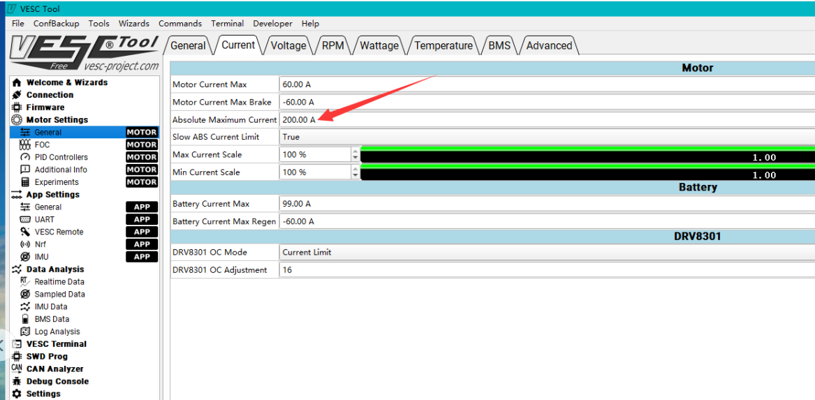
Image: Screenshot of VESC Tool interface, highlighting the 'Absolute Maximum Current' setting, which should be kept below 200A.
6. Operating Instructions
Once the ESC is correctly wired and configured using VESC Tool, you can begin operation. Ensure your battery is adequately charged and all connections are secure before powering on. The ESC supports various control inputs (PPM, ADC, NRF, UART) allowing for flexible integration with different remote controls and systems.
The ESC supports DC, BLDC, and FOC (sinusoidal) motor control modes. The optimal mode depends on your motor type and desired performance characteristics, which can be configured in VESC Tool.
7. Maintenance
- Regular Inspection: Periodically check all wiring connections for looseness or damage.
- Cleanliness: Keep the ESC clean and free from dust, dirt, and moisture. Use a soft, dry cloth for cleaning.
- Temperature Monitoring: Ensure the ESC operates within its recommended temperature range. Excessive heat can lead to reduced performance and component damage. Consider adding external cooling if operating in high-stress conditions.
- Firmware Updates: Only update firmware if necessary and follow the manufacturer's specific instructions, paying close attention to warnings regarding phase filtering and current limits.
8. Troubleshooting
- ESC Not Powering On: Check battery connections and ensure correct polarity. Verify battery voltage is within the ESC's operating range (14-84V).
- Motor Not Spinning/Irregular Operation:
- Verify motor phase wire connections.
- Check Hall sensor connections if using sensored mode.
- Ensure VESC Tool configuration matches your motor and setup.
- If using firmware 5.3 or above, confirm phase filtering is disabled.
- Overheating: Reduce load, improve airflow around the ESC, or consider adding active cooling. Check for short circuits in motor or wiring.
- ESC Damage After Firmware Update: This can occur if firmware 5.3+ is used without disabling phase filtering. Always follow specific update instructions and warnings.
- Unexpected Behavior: Re-check all VESC Tool settings. Avoid restoring default parameters if you have made specific adjustments for your setup.
9. User Tips
- The ESC is capable of handling 84V. While it has a continuous current of 100A and can handle 120 phase amps, users have reported pulling up to 180 phase amps. Be mindful of temperatures and consider adding cooling if pushing these limits.
- The controller can be used without a Hall sensor if your motor supports sensorless operation, configurable via VESC Tool.
- For dual drive setups, two single drive ESCs can be connected using a CANbus wire for synchronized operation.
10. Warranty & Support
The warranty period for consumable electronic products like this ESC is generally 2 months from the 7th day after shipment, as determined by logistic record. For non-electronic products, the warranty period is also 2 months from the 7th day after shipment.
The warranty may be voided under the following conditions:
- Mechanical damage to electronic components or PCB.
- PCB board has repair soldering iron traces (excluding solder the cable bullet connectors).
- Wire damage or external impact damage.
- Water damage (not waterproof products).
- Abnormal applications beyond the product specifications.
- Products purchased from channels other than Flipsky directly.
- For products transferred between users, the warranty is only valid once to the original order purchaser. If the original ordered product has been used, the warranty policy is invalid for subsequent transactions.
For warranty claims or technical support, please contact customer support with your purchase details.


