1. Introduction
The Y&H BL4600 series wind solar hybrid charge controller is designed for efficient management of power from both wind generators and solar panels to charge batteries. It features advanced Maximum Power Point Tracking (MPPT) technology for both charging methods, ensuring optimal energy conversion. This manual provides detailed instructions for the safe and effective installation, operation, and maintenance of your controller.
2. Product Features
- Industrial-grade main control chip with 16-level AD sampling accuracy for precise real-time display of temperature, charging current, discharging current, and cumulative power generation.
- Auto-focus MPPT tracking charging for high efficiency, with continuous detection and two-way focus tracking. Supports 15V to 40V boost MPPT charging.
- Large-screen LCD display with adjustable charging and discharging parameters for ultra-wide charge and discharge adjustments, enabling compatibility with various battery types (lead-acid, lithium with user-defined parameters).
- Adjustable output power-off time in minutes and hours for enhanced convenience.
- Complete 3-stage charge management to effectively protect the battery and extend its lifespan.
- Built-in protections: overheating, overcurrent, short circuit, open circuit, and reverse connection. The controller automatically recovers after fault elimination without equipment damage.
- Two-way MOS tube anti-backflow circuit for high-power charging mode and ultra-low heat generation.
- Multiple MOS integration for both charging and discharging, ensuring high-power performance and efficient heat dissipation via Phoenix wing aluminum alloy.
- Capable of supplying power to the load without a connected battery, functioning as a direct sunshine application.
3. Safety Precautions
WARNING: Failure to follow these safety instructions may result in injury or damage to the controller and other components.
- Ensure all connections are correct and secure before powering on the system.
- Strictly adhere to the recommended maximum input power for wind (200W) and solar panels (30A=300W, 40A=400W, 60A=600W, 100A=700W). Exceeding these limits can damage the controller.
- The voltage value of the solar panel should be approximately 1.5 times the voltage value of the battery being recharged.
- It is strictly forbidden to short-circuit the boost output power port.
- Always connect the battery first, then the solar panel or wind generator, and finally the load. Disconnect in reverse order.
- Do not reverse the polarity of any connections.
- This controller is suitable for lead-acid batteries (open, sealed, colloidal). For lithium batteries, user-defined parameters are required.
4. Installation and Connection
Follow these steps for proper system connection. Refer to the diagrams for visual guidance.
4.1 General Connection Steps
- Connect the positive and negative terminals of the battery to the controller. The controller will automatically detect the battery voltage.
- Connect the positive and negative terminals of the load to the controller. Ensure correct polarity.
- Connect the solar panel to the controller.
- Connect the wind generator to the controller.
- For boost charging function or power output, ensure no short circuits at any time.
4.2 Specific Connection Modes
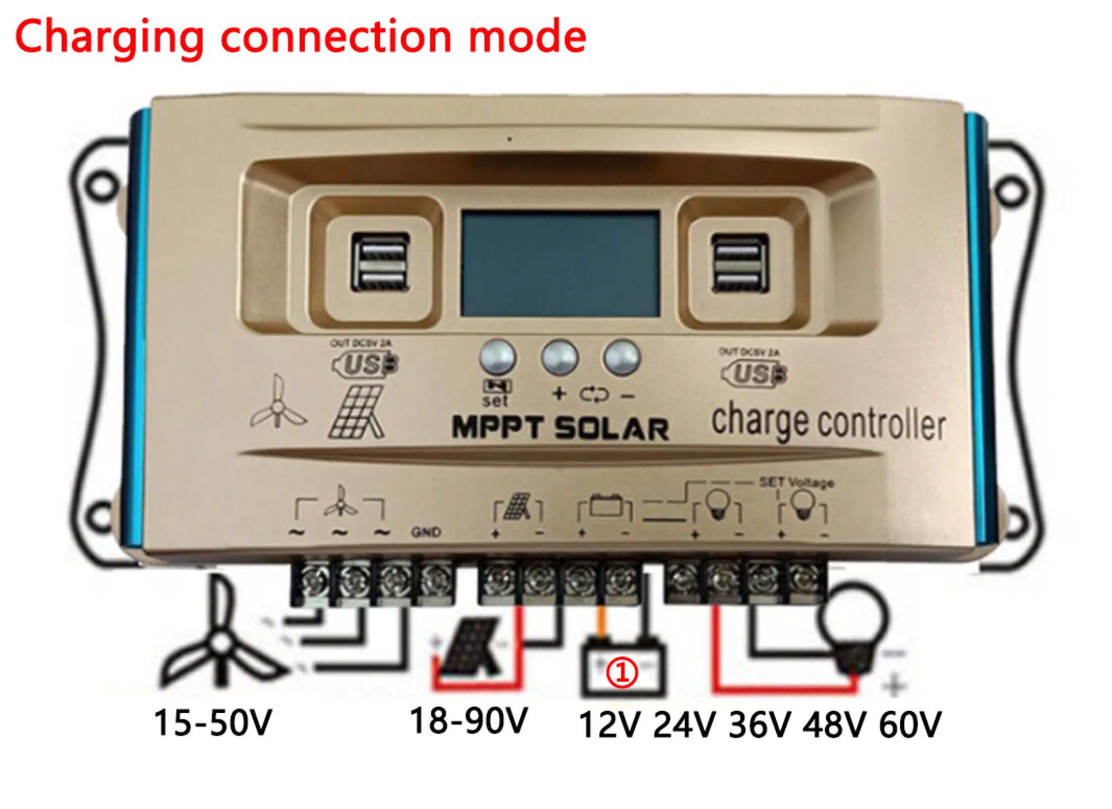
4.2.1 Standard Charging Connection Mode
In this mode, the wind input is 15V-50V, and the solar panel input is 18V-90V. It charges 12V, 24V, 36V, 48V, or 60V batteries. The output load voltage corresponds to the battery voltage. Connect the battery first, then the solar panel or wind motor, and finally the load. Set the corresponding voltage value for the rechargeable battery and relevant charging parameters; the controller has a memory function.
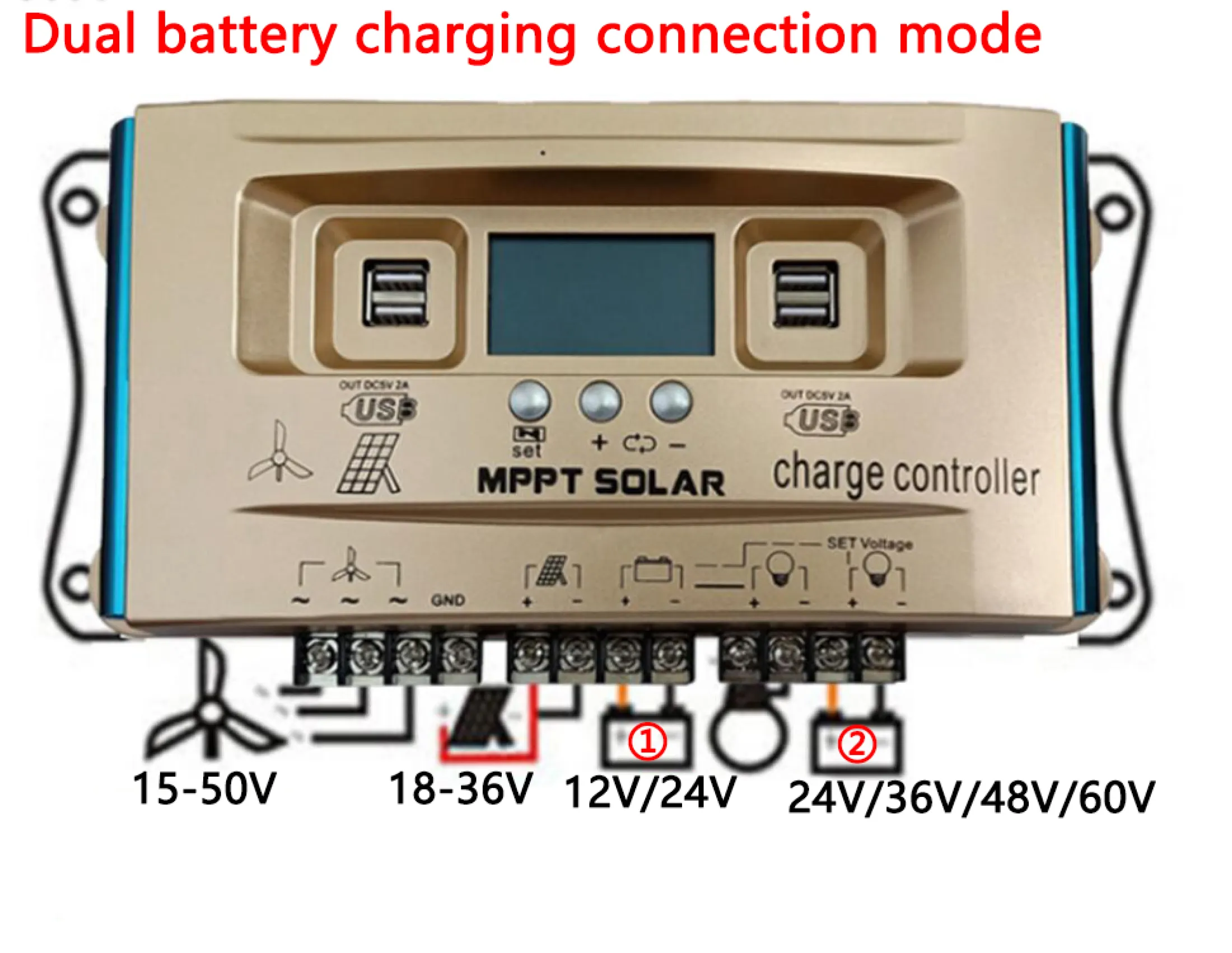
4.2.2 Dual Battery Charging Connection Mode
This mode supports charging two batteries simultaneously. For wind input 15V-50V and solar panel 18V input, it charges battery ① (12V) and battery ② (24V, 36V, 48V, 60V). For solar panel 36V input, it charges battery ① (24V) and battery ② (36V, 48V, 60V). The output load corresponds to the battery voltage. Connect batteries first, then solar/wind, then load. Set parameters for both batteries.
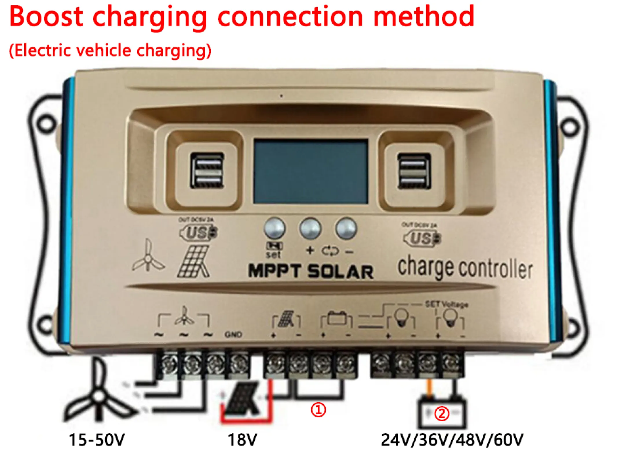
4.2.3 Boost Charging Connection Mode (Electric Vehicle Charging)
For wind input 15V-50V and solar panel 18V input, battery ① is not connected. Connect to the negative pole of battery ② (24V, 36V, 48V, 60V) for charging. For solar panel 18V-36V input, battery ① is not connected. Connect to the negative pole of battery ② (24V (PV18V), 36V, 48V, 60V (PV36V)) for charging. The output load corresponds to the battery voltage. Connect battery ② first, then solar/wind, then load. Set parameters for battery ②.
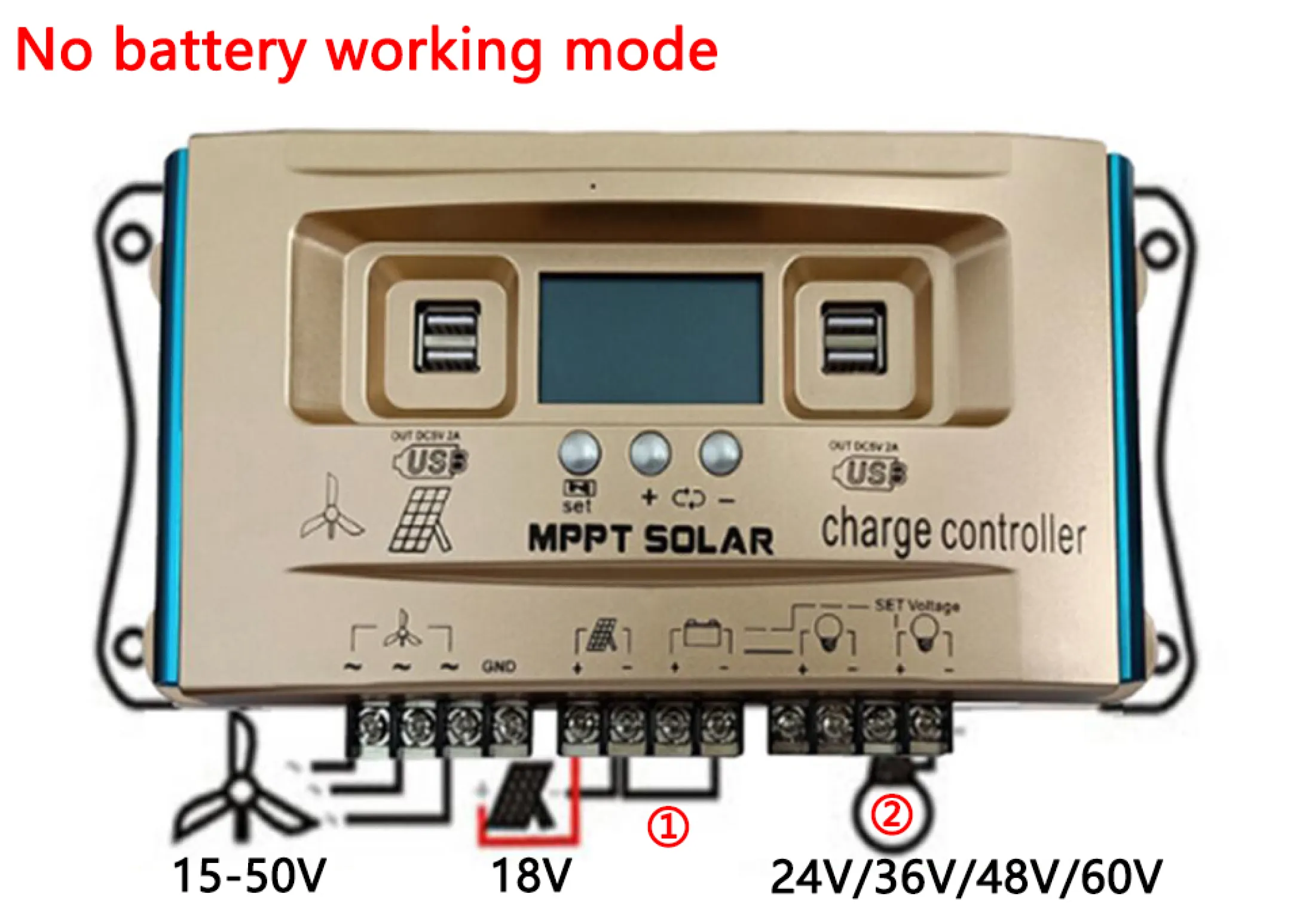
4.2.4 No Battery Working Mode
In this mode, the controller can drive a load directly without a battery. For wind input 15V-50V and solar panel 18V input, battery ① is not connected. Connect to the negative pole of load ② (24V, 36V, 48V, 60V) to drive it. The boost output voltage matches the load voltage. Connect the wind/hydraulic motor or solar panel (18V) first, then set the corresponding voltage value for the load, and finally connect the load. The controller retains settings with memory function.
5. Operation
5.1 LCD Display and Key Functions
The controller features an LCD screen and three buttons for navigation and parameter adjustment.
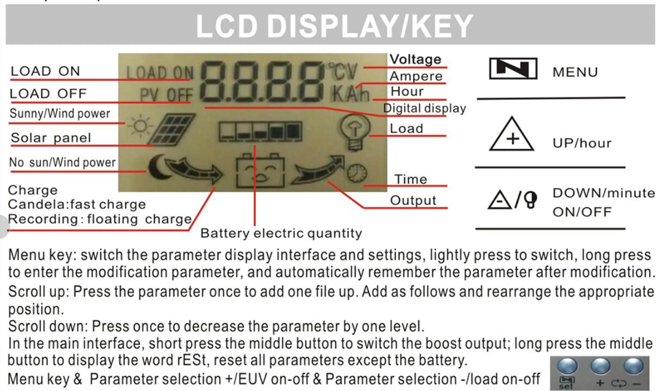
- MENU Key:
- Lightly press to switch between parameter display interfaces and settings.
- Long press to enter parameter modification mode. Parameters are automatically remembered after modification.
- UP/hour Key: Press once to scroll up through parameters or add one file up.
- DOWN/minute ON/OFF Key:
- Press once to decrease the parameter by one level.
- In the main interface, short press the middle button to switch the boost output.
- Long press the middle button to display "rESt" and reset all parameters except the battery.
5.2 Parameter Browsing and Setting
The controller allows you to browse various interfaces and set parameters to match your system's requirements.
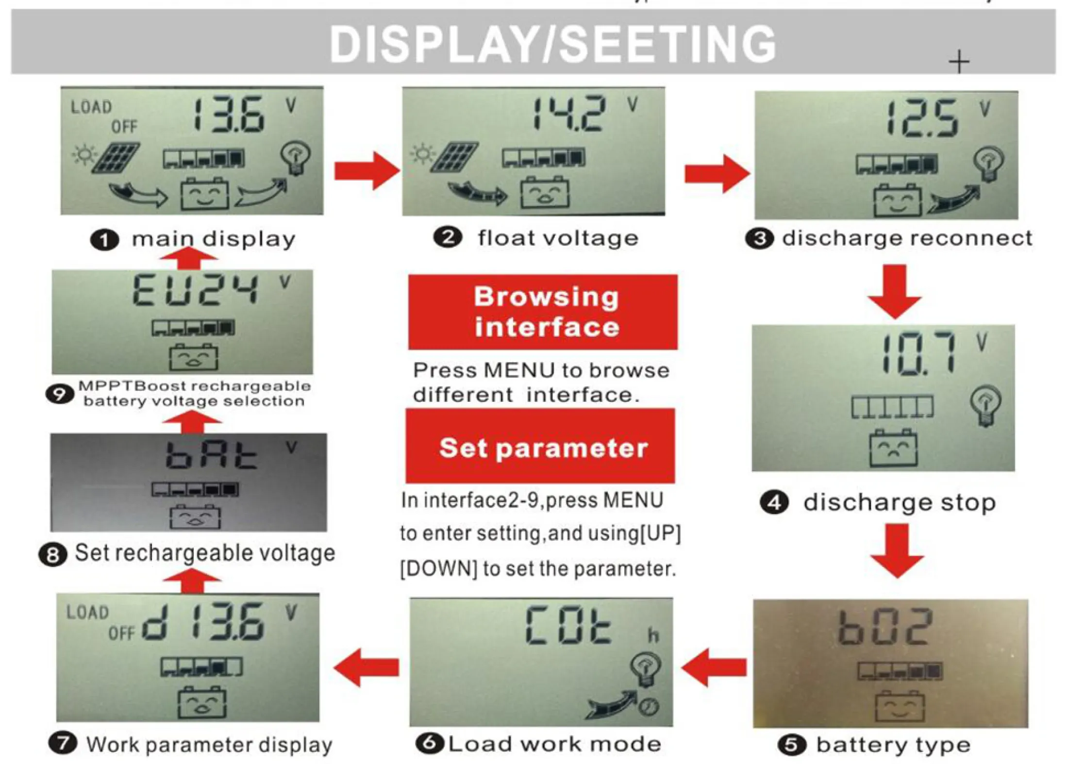
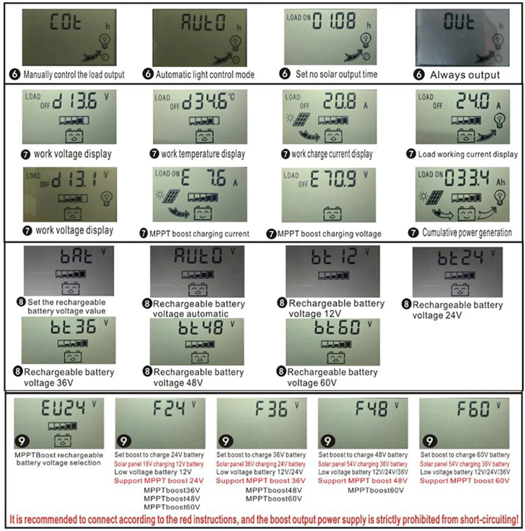
- Browsing Interface: Press the MENU button to cycle through different display interfaces (e.g., main display, float voltage, discharge reconnect, discharge stop, battery type, load work mode, work parameter display, rechargeable voltage setting, MPPT boost rechargeable battery voltage selection).
- Setting Parameters: In interface 2 (float voltage) or other relevant setting interfaces, press the MENU button to enter the setting mode. Use the UP and DOWN buttons to adjust the parameter values.
- Rechargeable Battery Voltage Selection: Use interface 9 (EU24, F24, F36, F48, F60) to select the MPPT boost rechargeable battery voltage.
- Rechargeable Battery Value Setting: Use interface 8 (bAE) to set the specific rechargeable battery voltage value.
6. Maintenance
Regular maintenance ensures optimal performance and longevity of your Y&H Wind Solar Hybrid Controller.
- Visual Inspection: Periodically check the controller for any visible damage, loose connections, or corrosion.
- Cleanliness: Keep the controller clean and free from dust and debris. Use a dry cloth to wipe the surface. Ensure ventilation openings are not blocked.
- Connection Checks: Verify that all wiring connections are tight and secure. Loose connections can lead to power loss or overheating.
- Environmental Conditions: Ensure the controller is installed in a well-ventilated area, away from direct sunlight, moisture, and corrosive substances.
- Parameter Review: Occasionally review the set parameters on the LCD to ensure they still match your battery type and system requirements.
7. Troubleshooting
This section addresses common issues you might encounter with your controller.
| Problem | Possible Cause | Solution |
|---|---|---|
| Controller not powering on / LCD blank |
|
|
| Battery not charging or charging slowly |
|
|
| Load not receiving power |
|
|
| Inaccurate readings on LCD |
|
|
8. Specifications
Detailed technical specifications for the Y&H BL4600 series Wind Solar Hybrid Controller.
| Feature | TY-WSC-30 | TY-WSC-40 | TY-WSC-60 | TY-WSC-100 |
|---|---|---|---|---|
| Rated Charge Current | 30A | 40A | 60A | 100A |
| Rated Discharge Current | 10A | 10A | 20A | 30A |
| Max Wind Input | 200W | |||
| Max Solar Input (30A) | 300W | |||
| Max Solar Input (40A) | 400W | |||
| Max Solar Input (60A) | 600W | |||
| Max Solar Input (100A) | 700W | |||
| Max Solar Input (12V/24V Battery) | 18V Solar Panel for 12V battery, 36V Solar Panel for 24V (<40V) | |||
| Max Solar Input (36V/48V Battery) | 54V Solar Panel for 36V battery and 72V Solar Panel for 48V (<80V) | |||
| Max Solar Input (60V Battery) | 60V battery is charged with 90V solar panel, voltage is less than 100V | |||
| Equalization 12V/24V (Lithium B01) | 12.2V/24.4V | |||
| Equalization 12V/24V (Gel B02) | 14.2V/28.4V | |||
| Equalization 12V/24V (Flood B03) | 14.6V/29.2V | |||
| Equalization 36V/48V (Lithium B01) | 37V/49V | |||
| Equalization 36V/48V (Gel B02) | 42V/56V | |||
| Equalization 36V/48V (Flood B03) | 44V/58V | |||
| Equalization 60V (Lithium B01) | 61V | |||
| Equalization 60V (Gel B02) | 71V | |||
| Equalization 60V (Flood B03) | 73V | |||
| 12V Float | 14.2V (default, adjustable) 12.0-15.0V | |||
| 12V Discharge Stop | 10.7V (default, adjustable) 9.0-11.5V | |||
| 12V Discharge Reconnect | 12.5V (default, adjustable) 11.0-13.0V | |||
| 24V Float | 28.4V (default, adjustable) 24.0-29.0V | |||
| 24V Discharge Stop | 19.0V (default, adjustable) 18.0-22.0V | |||
| 24V Discharge Reconnect | 22.0V (default, adjustable) 22.0-26.0V | |||
| 36V Float | 42.0V (default, adjustable) 36.0-45.0V | |||
| 36V Discharge Stop | 30.0V (default, adjustable) 27.0-33.0V | |||
| 36V Discharge Reconnect | 38.0V (default, adjustable) 36.0-42.0V | |||
| 48V Float | 56.0V (default, adjustable) 48.0-60.0V | |||
| 48V Discharge Stop | 40.0V (default, adjustable) 36.0-44.0V | |||
| 48V Discharge Reconnect | 50.0V (default, adjustable) 48.0-56.0V | |||
| 60V Float | 71.0V (default, adjustable) 60.0-75.0V | |||
| 60V Discharge Stop | 50.0V (default, adjustable) 45.0-55.0V | |||
| 60V Discharge Reconnect | 63.0V (default, adjustable) 60.0-70.0V | |||
| Self-Consume | <10mA | |||
| USB Output | 5V/2A Max | |||
| Operating Temperature | -10°C to +60°C | |||
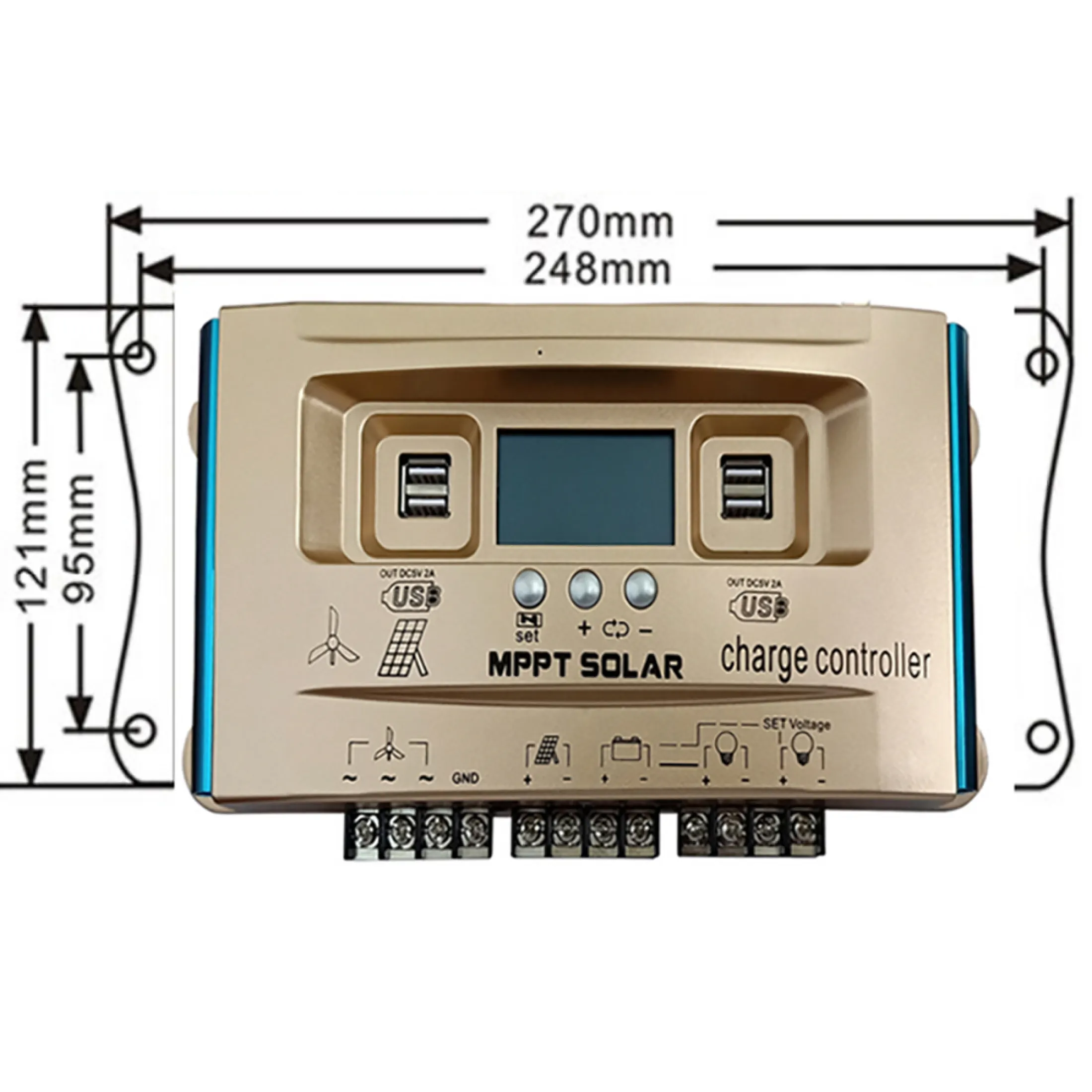
| Size/Weight | 268*138*66mm / 650g | |||
9. User Tips
- Verify MPPT Functionality: The controller is designed with MPPT charging. Ensure your solar panel voltage is appropriately matched to your battery bank for optimal MPPT performance (e.g., solar panel voltage ~1.5 times battery voltage).
- Adjustable Charging Parameters: Take advantage of the adjustable charging parameters to fine-tune the controller for your specific battery type (especially for lithium batteries) and desired charging profile. This can help prolong battery life.
- Voltage Compatibility: Always double-check that the input voltage from your solar panels and wind generator, as well as the output voltage for your battery and load, are within the specified ranges for your controller model to prevent damage.
10. Support
For further assistance or inquiries, please contact your retailer or the manufacturer's customer support. Ensure you have your product model number and purchase details ready.
Manufacturer: Y&H
Model Number: BL4600-30A/40A/60A/100A


