1. Introduction
Thank you for choosing the AISET NGG-3410V Series Temperature Controller. This intelligent temperature control instrument is designed for precise temperature regulation in various industrial and laboratory applications. This manual provides essential information for the safe and efficient installation, operation, and maintenance of your device. Please read this manual thoroughly before use and keep it for future reference.
2. Safety Information
Always observe the following safety precautions to prevent personal injury or damage to the instrument:
- Ensure the power supply voltage matches the specifications of the controller.
- Disconnect power before performing any wiring or maintenance.
- Do not operate the instrument in environments with flammable gases, corrosive substances, or excessive humidity.
- Only qualified personnel should perform installation and wiring.
- Avoid touching internal components when the device is powered on.
- Ensure proper grounding to prevent electrical shock.
3. Product Overview
3.1 Front Panel
The front panel features a dual digital display for Process Value (PV) and Set Value (SV), along with indicator lights and control buttons.

- PV Display (Red): Shows the current measured temperature (Process Value).
- SV Display (Green): Shows the desired set temperature (Set Value).
- OUT Indicator: Illuminates when the control output is active.
- ALM1 Indicator: Illuminates when Alarm 1 is active.
- ALM2 Indicator: Illuminates when Alarm 2 is active.
- AT Indicator: Illuminates during auto-tuning process.
- Buttons: Loop/Function, Left/Shift, Down, Up for navigation and setting adjustments.
3.2 Rear Panel and Terminals
The rear panel contains the terminal block for power input, sensor input, and control outputs.
4. Specifications
| Feature | Specification |
|---|---|
| Model Number | NGG-3410V Series (e.g., NGG-3400V, NGG-3410V-1, NGG-3430V, NGG-3000) |
| Material | ABS |
| Measurement Range | 0 ~ 400°C (K-type thermocouple) |
| Accuracy | 0.5 Class |
| Power Supply | 100-240VAC, 50Hz, 5VA |
| Origin | Mainland China |
5. Installation & Wiring
5.1 Mounting
The temperature controller is typically designed for panel mounting. Ensure adequate space for ventilation and access to wiring terminals. Cut a panel opening of appropriate dimensions for the controller to fit snugly.
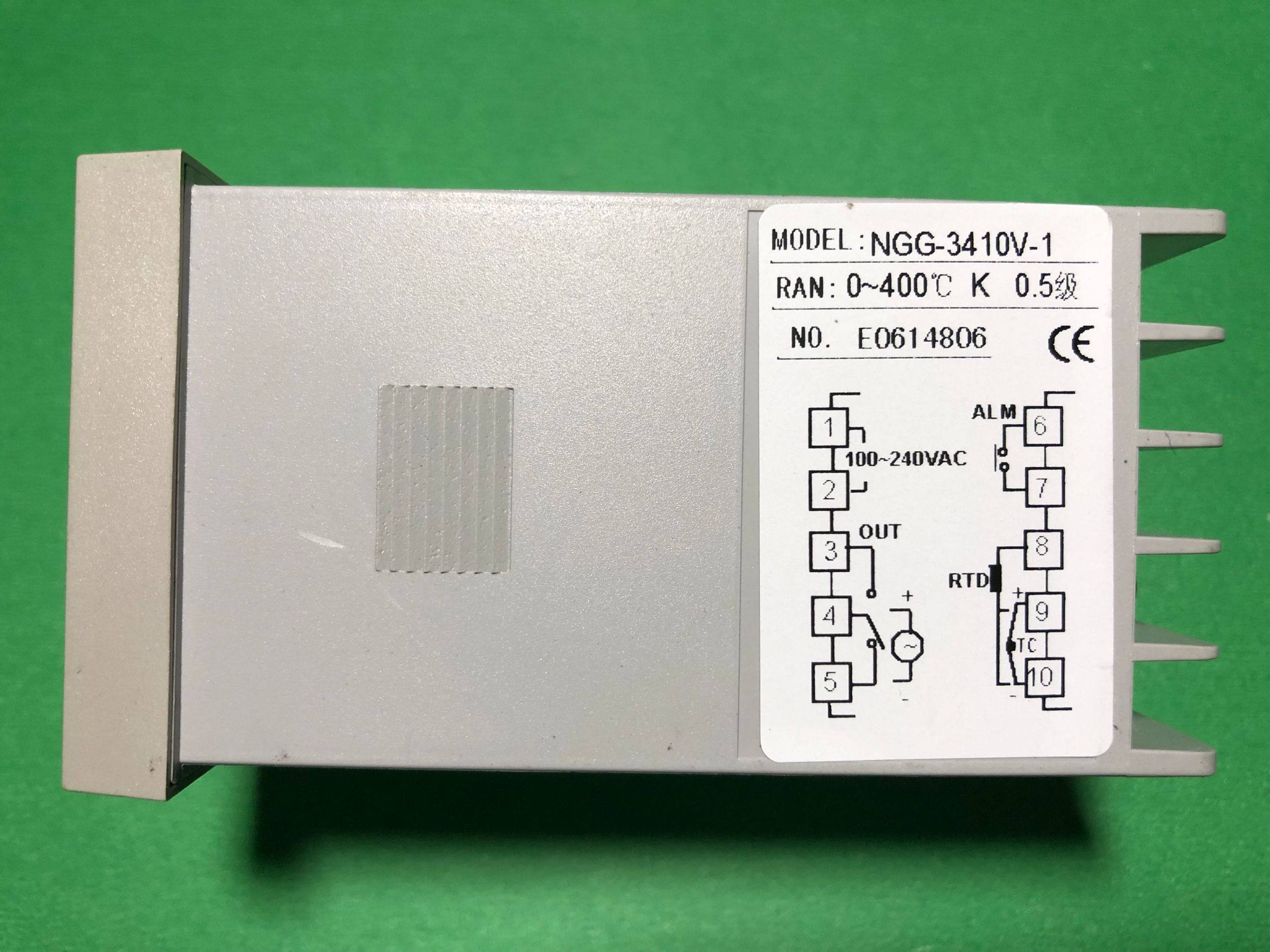
5.2 Wiring Diagram
Refer to the wiring diagram below for correct connections. Incorrect wiring can damage the instrument or connected equipment.

Terminal Connections:
- Terminals 1 & 2: Power Input
Connect your 100-240VAC, 50Hz power supply to these terminals. - Terminals 3, 4, 5: Control Output (OUT)
These terminals provide the control output, typically a relay contact. Connect your heating/cooling element or other controlled device here. Terminal 3 is common, Terminal 4 is normally open (NO), and Terminal 5 is normally closed (NC). - Terminals 6 & 7: Alarm Output (ALM)
These terminals provide the alarm output. Connect your alarm indicator or device here. - Terminals 8, 9, 10: Sensor Input (RTD/TC)
- For RTD (Resistance Temperature Detector) sensor: Connect the RTD sensor to terminals 8, 9, and 10.
- For TC (Thermocouple) sensor (e.g., K-type): Connect the thermocouple to terminals 9 and 10. Ensure correct polarity.
Warning: Always ensure power is disconnected before making or changing any wiring connections.
6. Operating Instructions
6.1 Power On and Display
Once correctly wired and powered on, the controller will display the current Process Value (PV) in the red display and the Set Value (SV) in the green display. The indicators (OUT, ALM1, ALM2, AT) will light up according to their respective states.
6.2 Setting the Set Value (SV)
- Press the Loop/Function button (circular arrow) briefly to enter the SV setting mode. The SV display will start flashing.
- Use the Up (triangle pointing up) and Down (triangle pointing down) buttons to adjust the desired temperature.
- Use the Left/Shift button (left arrow) to shift the digit for faster adjustment.
- Press the Loop/Function button again to confirm the new SV and exit the setting mode.
6.3 Understanding Indicators
- OUT: Indicates that the control output is currently active (e.g., heating element is on).
- ALM1/ALM2: Indicates that the respective alarm condition has been met.
- AT: Indicates that the auto-tuning function is currently running.
6.4 Advanced Settings (Parameter Menu)
To access advanced parameters (e.g., PID parameters, alarm types, input sensor type, auto-tuning initiation), press and hold the Loop/Function button for several seconds until the display changes to show parameter codes. Use the Up, Down, and Left/Shift buttons to navigate and adjust parameters. Refer to the full product manual (if available from the manufacturer) for a complete list and explanation of all parameters.
7. Maintenance
- Cleaning: Wipe the front panel with a soft, dry cloth. Do not use abrasive cleaners or solvents.
- Inspection: Periodically check wiring connections for tightness and signs of wear or corrosion.
- Environment: Ensure the operating environment remains within specified temperature and humidity ranges.
No user-serviceable parts inside. Refer all servicing to qualified personnel.
8. Troubleshooting
| Problem | Possible Cause | Solution |
|---|---|---|
| No display after power on | No power supply or incorrect wiring | Check power connections (Terminals 1 & 2) and ensure voltage is within range. |
| PV display shows 'HHHH' or 'LLLL' | Sensor open circuit or short circuit, or incorrect sensor type setting | Check sensor wiring (Terminals 8, 9, 10). Verify sensor type in advanced settings. Replace faulty sensor. |
| Output (OUT) not activating | SV not reached, control mode issue, or faulty output wiring | Check SV and PV values. Verify output wiring (Terminals 3, 4, 5). Check control parameters in advanced settings. |
| Temperature unstable | Incorrect PID parameters or sensor placement | Perform auto-tuning (AT function). Ensure sensor is correctly placed and making good contact. |
9. User Tips
No specific user tips are available from customer reviews or Q&A at this time. Always refer to the detailed wiring diagram and ensure all connections are secure before powering on the device.
10. Warranty and Support
For warranty information, technical support, or service inquiries, please contact your original point of purchase or the manufacturer directly. Keep your purchase receipt as proof of purchase.