
1. Introduction
The GODIAG GT100 is a versatile OBD II 16PIN Break Out Box and ECU Connector designed for comprehensive automotive diagnostics, maintenance, programming, and coding. This device serves as a test platform for ECUs, allowing technicians and enthusiasts to perform various tasks with enhanced control and safety. It supports communication protocol detection, facilitates single and multiple ECU connections, and provides a stable power supply for diagnostic and programming tools.

2. Key Features
- ECU Connection & OBDII Protocol Detector: Facilitates communication detection and connection for ECU maintenance, diagnosis, programming, and coding.
- Extended Cable Functionality: The main cable can be extended, and optional dedicated adapters are available for various connection scenarios.
- Broad Compatibility: Works seamlessly with programming tools from major brands such as LAUNCH, AUTEL, FOXWELL, XHORSE, VXDIAG, and others.
- OBD1 to OBD2 Conversion: Capable of converting OBD1 diagnostic interfaces to the standard OBD2 diagnostic interface.
- BMW-CAS4 Adapter Platform: Supports testing platforms like the BMW-CAS4 adapter for key programming verification.
- Real-time Voltage Display: Monitors and displays the vehicle's OBDII interface voltage in real-time.
3. Package Contents
The GODIAG GT100 package includes the following items:
- 1 x GODIAG GT100 Host Unit
- 1 x OBD 2-in-1 Extension Cable
- 1 x Colored Jumper Cable
- 1 x 12V Power Supply Adapter
- 1 x 120 Ohm Resistance
- 6 x Banana Plugs
- 24 x Wire Accessories (Dupont 2.54mm connector female pins)

4. Setup Instructions
Follow these steps to set up your GODIAG GT100 for various operations:
- Connect the OBD 2-in-1 Extension Cable: Plug the OBD 2-in-1 extension cable into the GT100 unit. This cable will connect to your diagnostic tool.
- Connect the Power Adapter: Plug the 12V power adapter into the GT100 unit.
- Connect to ECU (if applicable): Use the colored jumper cables to connect the GT100 to the ECU. Refer to the specific wiring diagram for your ECU. If the ECU uses CAN protocol, ensure a 120 ohm resistor is connected if required.
- Connect to Vehicle OBD2 Port (if applicable): For in-vehicle diagnostics, connect the GT100 to the vehicle's OBD2 port.
- Power On: Turn on the power switch on the GT100. The device will display the current vehicle battery voltage.

5. Operating Instructions
The GODIAG GT100 offers several functionalities to assist in automotive diagnostics and programming.
5.1. Communication Protocol Detection
When a diagnostic or programming tool is connected to the GT100's OBD2 port, and the car model and function are selected, the protocol indicator lights on the GT100 will illuminate or flash. This indicates that the tool is sending a communication signal. If no indicator lights up, it suggests an incorrect connection or a damaged diagnostic tool.

After connecting the GT100 to the vehicle's OBD2 port and turning on the power switch, the current vehicle battery voltage will be displayed. When the diagnostic tool communicates with the vehicle, the corresponding protocol indicator light on the GT100 will turn on or flash, helping to identify the vehicle's communication protocol.
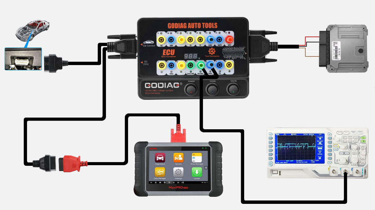
5.2. ECU Connection (Single Module)
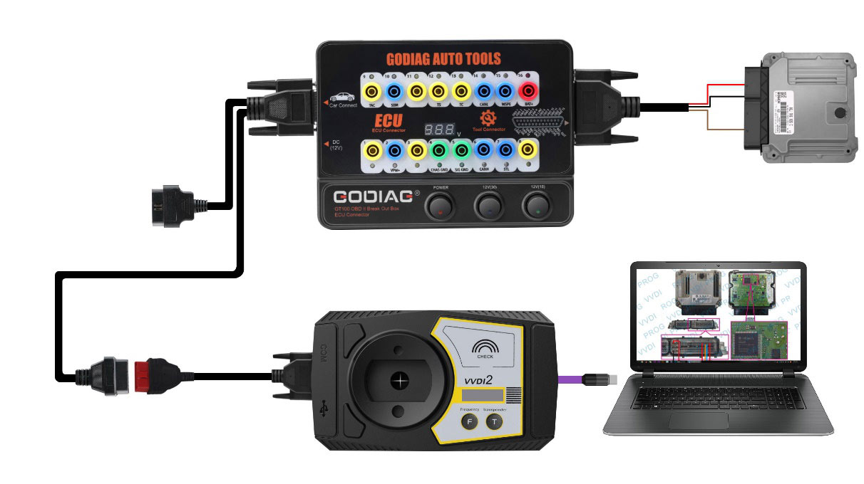
The GT100 allows for quick communication with a single ECU on a workbench. This is useful for engineers and technicians to perform single-module diagnosis and programming in an office environment, reducing the risk of data loss in other modules when testing directly on the vehicle.
- Connect the ECU using the colored jumper cables.
- Power the GT100 via the car's OBDII diagnostic interface or an AC power adapter.
- Connect your diagnostic tool or ECU programmer to the GT100 to diagnose and program the single ECU.
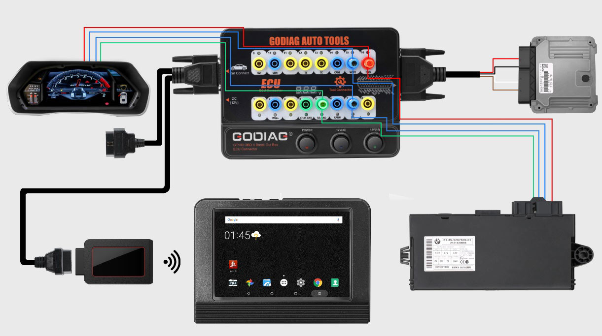
5.3. Multiple ECU Module Connection
For tasks requiring connection to multiple ECUs, such as key programming, the GT100 facilitates connecting several ECU modules simultaneously for detection and maintenance.
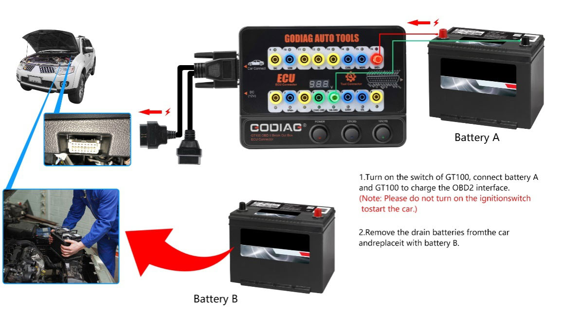
5.4. Power Supply During Battery Replacement
The GT100 can provide a stable power supply to the vehicle's ECU when replacing the car battery. This prevents malfunctions or loss of immobilizer remote data that can occur when the battery is disconnected.
5.5. OBD1 to OBD2 Conversion
The GT100 can convert an OBD1 diagnostic port or other special vehicle diagnostic ports to a standard OBD2 diagnostic port, allowing modern diagnostic tools to be used on older or specialized vehicles.

5.6. BMW-CAS4 Adapter Testing Platform
The GT100 can be integrated with testing platforms like the BMW-CAS4 adapter to verify the functionality of programmed keys with the CAS4 system.

5.7. Indicator Light Meaning
The GT100 features indicator lights for each pin on the OBD2 connector, providing visual feedback on communication and power status.
| Pin Number | Function |
|---|---|
| 1 | Manufacturer custom |
| 2 | SJE1850 wire |
| 3 | Manufacturer custom |
| 4 | Power grounding |
| 5 | Signal grounding |
| 6 | SAEJ2284 (CAN) high |
| 7 | ISO9141-2 & ISO/DIS 4230-4K wire |
| 8 | Manufacturer custom |
| 9 | Manufacturer custom |
| 10 | SJE1850 wire (bus-) |
| 11 | Manufacturer custom |
| 12 | Manufacturer custom |
| 13 | Manufacturer custom |
| 14 | SAEJ2284 (CAN) low |
| 15 | ISO9141-2 & ISO/DIS 4230-4L wire |
| 16 | Car battery positive |

5.8. Video Demonstration
Video 1: Demonstrating ThinkCar Pro reading DTCs using GODIAG GT100 to connect a Bosch ECU.
6. Specifications
| Item | Specification |
|---|---|
| Diagnostic Port | OBDII |
| Working Voltage | DC 9V-24V |
| Work and Power Consumption | 0.5-0.6W |
| Adapter Power | Input AC100V-240V, Output DC12V 1A |
| Operating Temperature Range | -20 to 70 °C (-4 to 158 °F) |
| Storage Temperature Range | -40 to 85 °C (-40 to 185 °F) |
| Dimensions (L x W x H) | 23cm x 18cm x 7cm |
| Item Weight | 1kg |
| External Testing Certification | CE |
| Material | Best Quality |
| Item Type | Car Diagnostic Cables and Connectors |
| Feature | Compatible with a lot of devices |
7. Troubleshooting
- Q: Will the GT100 work on 24-volt truck systems?
- A: Yes, the GT100 is designed to work on 24V truck systems.
- Q: Can I use the GT100 with my existing diagnostic tools (e.g., Autel, Launch)?
- A: Yes, the GT100 is compatible with a wide range of diagnostic and programming tools, including those from Xhorse VVDI2, Autel, Launch, Foxwell, and Vident.
- Q: Can the GT100 be used for programming ECUs, immobilizers, and clusters on a workbench?
- A: Yes, the GT100 facilitates connecting to ECUs, immobilizers, and clusters for programming and diagnostic tasks on a workbench.
- Q: Does the GT100 simulate sensors like CKP/CMP or injectors?
- A: The primary functions of the GT100 include communication protocol detection, ECU connection, and providing stable power. It does not explicitly list sensor or injector simulation capabilities.
8. User Tips
- Always ensure the GT100 is properly connected and powered before initiating any diagnostic or programming procedures.
- Monitor the real-time voltage display on the GT100. If the voltage drops below 11V, discontinue operations to prevent potential damage or data loss to vehicle modules.
- When connecting to an ECU with CAN protocol, verify if a 120 ohm resistor is required for stable communication.
- Familiarize yourself with the pinout diagram and indicator light meanings to quickly identify communication protocols and power status.
9. Warranty and Support
The GODIAG GT100 comes with a 1-year warranty from the date of purchase.
For technical assistance, troubleshooting, or warranty claims, please contact GODIAG Official Store customer support. Ensure you have your purchase details and product serial number available when contacting support.