Advantage Controls NANO XL Microprocessor-Based Controllers

Specifications
- Product Name: NANO XL
- Type: Microprocessor-based controller
- Designed for: Recirculating water treatment systems
- Control Functions: Conductivity monitoring and control, addition of chemicals, relay output activation
Product Usage Instructions
Installation
Follow the steps outlined in the Installation section of the manual to set up the NANO XL controller in your water treatment system.
Configuration
Use the front panel keypad to configure the controller according to your specific application needs. Refer to the Model Numbering table to determine the functions and features of your unit.
Conductivity Control
The NANO XL allows for conductivity monitoring and control of Total Dissolved Solids (TDS) in recirculating water systems. Select the conductivity scale from low, mid, or high ranges in the Configure menu.
Feed Timer Programming
Program the three selectable timers for various functions such as chemical addition or device activation. Each timer can be individually configured based on your requirements.
FAQ
Q: How can I determine the features of my NANO XL unit?
A: Check the model number label located on the controller enclosure to identify the base control function and optional features included in your unit.
Q: What is the purpose of conductivity control in water treatment systems?
A: Conductivity control helps monitor and regulate the level of Total Dissolved Solids (TDS) in recirculating water, ensuring optimal water quality.
Introduction
- NANO XL microprocessor-based controllers are designed to provide a wide range of control functions for recirculating water treatment systems.
- The controller is programmed through a front panel keypad and can be configured to provide a customized control system for your application.
- Your particular unit’s functions can be determined by comparing the unit’s model number to the Model Numbering table listed below.
Model Numbering
- NanoTron units have several base system control functions and unit optional features. Your unit may be supplied with one or more of the features described in this manual.
- To determine what features apply to your unit check the model number label located on the controller enclosure.
Base Control Function
- B2 – Boiler Conductivity and 3 Feed Timers
- C – Tower Conductivity and 3 Feed Timers
- F4 – Four Selectable Feed Timers
Whole Unit Optional Features
- A – Conduit Connections
- A3 – Conduit with CE
- E – Flow Switch
Description
- NanoTron units are designed to automate conductivity control and/or the addition of various chemicals or activate other devices via a relay output.
- Each relay can have its activation function selected from available analog inputs, timers, alarms, or utility.
NANOXL-C and NANOXL-B2 units include:
- Two totalizing water meter inputs can be configured for contacting head or hall effect meter inputs.
- Three digital inputs that can be set to disable a relay output.
- Four mechanical relay outputs with normally open and normally closed contacts can be configured for powered or dry contact relay operation.
- Conductivity Control (C & B) – Conductivity monitoring and control of Total Dissolved Solids (TDS) in recirculating water systems in terms of electrical conductivity measured in MicroSiemens/cm.
- The conductivity scale can be selected from three ranges (low, mid, and high) in the Configure menu (see page 12). Selectable feed timers are also included (see timer description below).
- Feed Timer – Three selectable timers that can be individually programmed as one of the following types:
- Pulse Timer – Accepts dry contact pulses from a water meter (supplied separately). It can accumulate 1- 9999 pulses to activate the timer to run from 0-99 minutes, 59 seconds in minutes and seconds. The timer will store up to 5 additional activations during an individual run time.
- Recycle Timer – Provides a user-defined “off” cycle in HH: MM and a user-defined “on” cycle in MM: SS that is repeated constantly.
- 28-DayTimer – 28-day feed timers, typically used for biocide feed are based on a 28-day cycle with two independent programmable feed cycles allowing for feed on selectable days and weeks.
- Post Bleed Timer – The relay is activated after a bleed cycle and runs for the set percentage of that bleed cycle.
- With Bleed Timer – Activates the relay output simultaneously with the bleed and limits the amount of time the relay output will be on during the bleed cycle.
- Utility – Relay always on
- Alarm – Relay on with alarms
Intended Use
 The NanoXL is a microprocessor-based measuring and control instrument used to measure water quality parameters and other process variables in a wide range of water and wastewater treatment applications.
- Operating the instrument in any way other than as described in these instructions may compromise the safety and function of the measuring system and is therefore impermissible.
- Electrical connection work and maintenance work may only be carried out by qualified personnel. The manufacturer is not liable for damage caused by improper or non-designated use.
Mechanical Specifications
| Enclosure Material | (ABS) “Polylac” |
| Enclosure | UL rated at 94V-0. Heavy duty, high-impact thermoplastic with pad-lockable gasketed Lexan viewing door. |
| Dimensions | W 7.5” (19.05 cm) x H 7.5” (19.05 cm) x D 5.875” (14.923 cm) |
| Operating Ambient Temp | 0° to 125°F (-17 to 52°C) |
| Storage Temperature | -4 – 176°F (-20 – 80°C) |
| Humidity | 10 to 90% non-condensing |
| Pollution Degree | 2 |
| Overvoltage Category | II |
| Altitude | 2000 m (6560 ft) maximum |
| Relays | 2.5 amp per relay |
Icon Definitions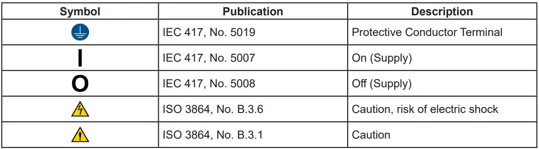
Installation
A. Electrical Wiring Information
- The controller has an internal regulated power supply that will operate in the range of approximately 100 to 240 VAC on the incoming wiring. Output relay(s) are protected with a replaceable fuse. The relay output voltage will equal the incoming line voltage.
- Your controller will arrive from the factory prewired or ready for hardwiring. Depending on your configuration of controller options, you may be required to hardwire some or all of the input/output devices. Refer to the logic and relay card wiring section.
- Note: When wiring the optional flow meter contactor input, the 4-20 mA outputs, or a remote flow switch, it is advisable to use stranded, twisted, shielded pair wire between 22-26 AWG.
- The shield should be terminated at the controller at the most convenient shield terminal.
- Prewired units are supplied with a 16 AWG cable with a 3-wire grounded USA 120-volt plug for incoming power and 18 AWG 3-wire grounded receptacle cords for all control relay outputs.
- Conduit units are supplied with liquid tights and adaptors for easy hard wiring to the supplied connector.
 CAUTION CAUTION |
|
| 1. | There are live circuits inside the controller even when the power switch on the front panel is in the OFF position!
The front panel must never be opened before power to the controller is REMOVED! If your controller is prewired, it is supplied with an 8-foot, 18 AWG power cord with a USA-style plug. A tool (#1 Phillips driver) is required to open the front panel. |
| 2. | Low voltage signal wires (probes, flow switches, water meters, etc.) should never be run in conduits with high voltage (like 115VAC) wires. |
| 3. | Never attempt to land connections to the controller without first disconnecting power from the outlet. |
| 4. | Do not block access to disconnect power during mounting and installation. |
| 5. | The electrical installation of the controller must be done by trained personnel only and conform to all applicable National, State, and Local codes! |
| 6. | Proper grounding of this product is required. The controller should be connected to its isolated circuit breaker, and for the best results, the ground should be a true earth ground, not shared. Any attempt to bypass the grounding will compromise the safety of persons and property. |
| 7. | Operating this product in a manner not specified by the manufacturer may impair the protection provided by the equipment. |
| 8. | Only power device with cover installed. Never operate the device with the cover removed. |
Additional Notes:
- Liquid tight fittings and some labeled signal leads are provided for signal (low voltage) connections, such as water meter inputs.
- Hall effect meters that require +12 VDC must use an external power supply (TFS-PWR).
- Optional 4-20mA ouput is produced with 12 VDC on the loop. Do not connect output to devices that are trying to power the loop.
Mounting Location Information
- Select a mounting location that provides the operator easy access to the unit and a clear view of the controls through the cover of the controller. The location should be convenient to ground electrical connections, and the needed sample line plumbing, and is on a stable vertical surface.
- Do not block access to disconnect power during mounting and installation.
- Avoid mounting in locations that expose the controller to direct sunlight, vapors, vibration, liquid spills, or extreme temperatures; less than 0°F (-17.8°C) or greater than 120°F (50°C). EMI(electromagnetic interference) from radio transmissions and electric motors can also cause damage or interference and should be avoided.
- The minimum screw/bolt size is #8 or larger.
Logic and Relay Cards
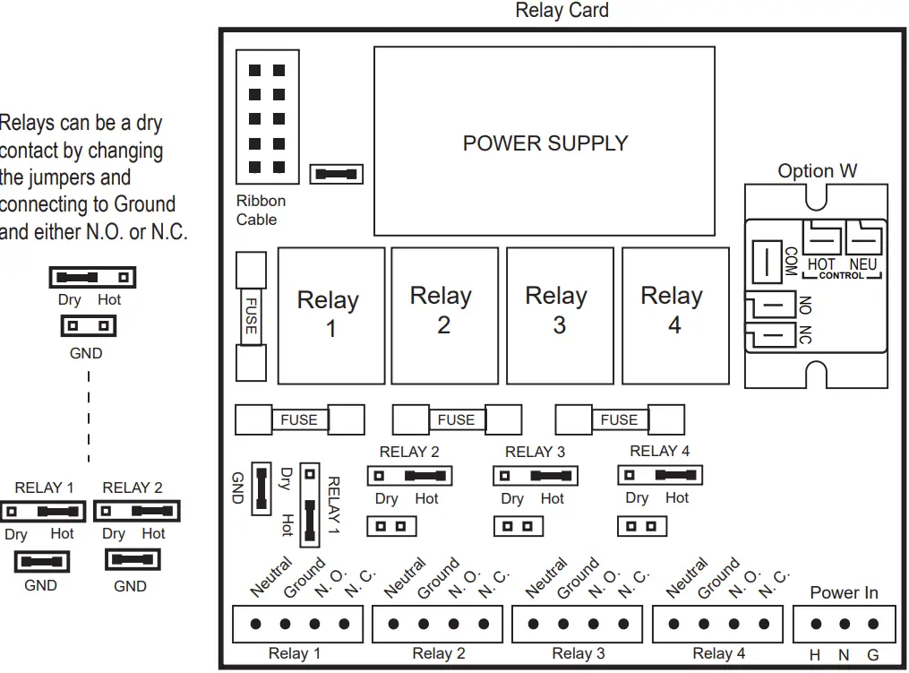
Nano XL-C Logic Card
Electrode Installation
- Controllers may come configured for various circulating water systems. Listed below are instructions for cooling tower and boiler typical installations.
- Your specific installation requirements may differ but should conform to these instructions as much as possible for proper operation.
A. Cooling Tower
- The standard probe(s) and/or flow assembly for cooling tower installations are constructed of schedule 80 PVC and supplied with 3/4” slip fittings for installation into a sample line.
- To ensure proper operation the sample line must have a flow rate of 3-10 gpm.
- Inlet pressure must be higher than outlet pressure for water to flow past the electrode(s) to achieve the required rate.
- The probes are temperature-compensated for increased accuracy.
Notes:
- Install an isolation valve on either side of the flow assembly so electrodes can be easily isolated for removal and cleaning.
- A line strainer is recommended upstream from the probes to protect against fouling and damage.
- Systems with a flow switch require a 2-3 gpm flow rate to operate outputs.

WARNINGS:
- Electrodes are O-ring sealed, which if damaged will cause a leak.
- Do not allow pH sensor tips to dry out, damage will occur.
- Do not exceed a water temperature range of 32°F to 140°F.
- Do not exceed a maximum pressure of 150 psi.
Typical Cooling Tower Installation Diagram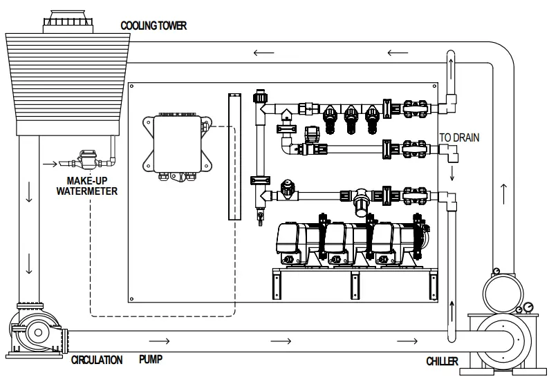
B. Boiler
- Standard boiler electrodes have an MNPT stainless steel bushing and are supplied with an FNPT cross designed for mounting in the skimmer (surface) blowdown line.
- Sampling of the boiler’s water can be achieved using one of two typical plumbing configurations (continuous sampling or timed and/or hold sampling).
- For a successful installation, it is critical to observe the recommended distances and pipe sizes provided in the installation drawings.
- For best results, the electrode cross should be mounted in a 1 ”skimmer blowdown line within 4’ of the boiler. Smaller line sizes and greater distances may affect the response time and accuracy of the electrode.
- A flow-throttling device downstream from the probe (within 24 inches) is required to ensure that the electrode is exposed to water and not steam.
- Properly installed and adjusted, this device will prevent flashing in the electrode chamber.
Notes:
- Install a fully ported type valve between the electrode and the boiler. This allows the electrode to be isolated for removal and cleaning.
- A flushing line and 1/4 turn type ball valve should be installed in the bottom of the cross to periodically “flush” sediment from the electrode chamber.
- Make sure the alignment arrows on the probe end up parallel to the flow for best performance.
WARNINGS:
- The probe must be fully immersed in the system water to read correctly.
- Steam flashing will result in incorrect readings.
- Do not exceed a maximum water temperature of 436°F (224°C)
- Do not exceed a maximum pressure of 350 psi (24.1 bar)
- A throttling device must be installed downstream from the electrode.
Boiler Conductivity Electrodes

Wiring Note: BE-32 probes require a (2) conductor cable from the controller to probe. The (2) wires connect on the (2) conductivity points (R & B) as shown.
Typical Continuous Sampling Boiler Installation Diagrams
WARNING – Do not use on bottom blowdown lines, only continuous or surface blowdown lines!
Typical Timed Sampling and Sample and Hold Boiler Installation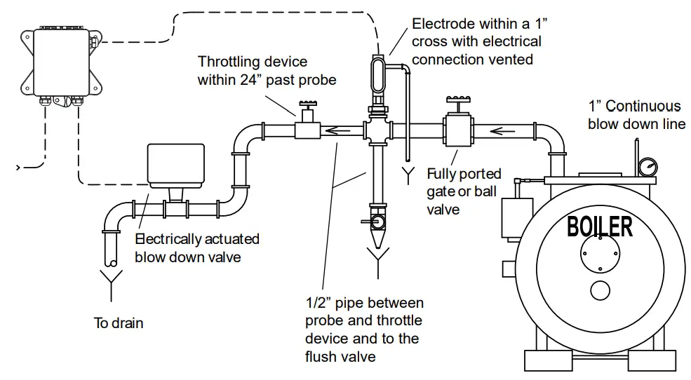
WARNING – Do not use on bottom blowdown lines, only continuous or surface blowdown lines!
Front Panel Description

System Operation Overview
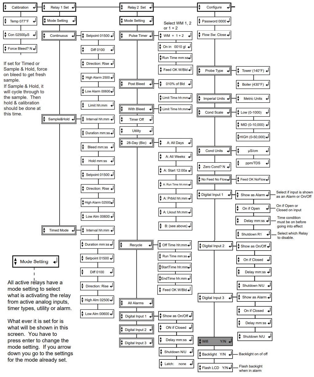
Description of Menus
- NANOXL controllers have two modes of operation, Run and Menu. All menus are circular. Pressing the DOWN key will display the next line of information on the display.
- Run – This mode is for normal operation. In the Run mode, the display will read system values. If an alarm is present, the display flashes with the alarm status.
- The Run menu will display values such as day, time, date, and other values depending upon the features present on the unit. The unit will automatically return to the Run mode if no keys are pressed for three minutes.
- Menu – This mode is used to make adjustments to settings and readings on the controller. To access the Menu mode from the run screen, press the Menu key.
- Use the up or down arrow to scroll through the various menus. When you want to access a specific menu, press the Enter key.
- Once you have entered a sub-menu you will be able to step through that menu’s options with the up or down arrow key.
Conductivity Sampling Methods
- A. Continuous – Typical for most tower applications. The controller is constantly reading the sensor and activating the bleed relay based on the reading’s relationship to the set point, set point direction, and differential.
- Example: A rising set point of 1500 and differential of 50 the bleed relay would activate when the conductivity rises above 1500 and stays on until the reading drops to 1450.
- B. Timed Sampling – A sample timer allows the conductivity to be sampled at periodic intervals.
- Sample intervals are adjustable from 1 minute to 9 hours, 59 min. Sample duration (on-time) is adjustable from 1 second to 99 minutes, 59 seconds. If the reading is below the set point by the differential amount the bleed relay will be turned off at the end of the sample duration and the sample interval countdown reinitiated. If the reading is above the set point at the end of the sample method the bleed relay stays on until the reading drops by the differential amount.
- C. Sample and Hold – Also uses a sample timer for periodic sampling intervals. The unit will sample for its duration and then hold the blowdown valve closed for a settable period (hold time). The conductivity is checked at the end of the hold period, if additional blowdown is required the blowdown valve is held open for a preset amount of time (blowdown time). Then sample cycle is repeated until the reading is below the set point at the end of a hold cycle and the sample interval countdown is reinitiated.
- Note: Timed Sampling and Sample and Hold are typically used for boiler applications but Timed sampling can also be used on small towers. On these tower applications, the probe is installed in the bleed line before the bleed valve.
Calibration Overview
- The NanoTron controllers update the conductivity reading every two seconds with a running average. The Nanotron controller’s conductivity scale should be selected so that the conductivity setpoint is as close as possible to the middle of the scale. (See page 12 menu for setting scale).
- Note: If a controller is using Timed Sampling or Sampling and Hold methods of control the conductivity reading shown in the RUN mode may not be a current reading. The controller will hold and display the conductivity value seen at the end of the last sample or hold duration. To see a current reading force on the bleed relay with either the Force button or via the Calibration menu.
- A. Continuous – Calibrating continuous sampling units can be done at any time with the probe in a steady stream of water with no air or steam present.
B. Timed Sampling – While in the calibration menu, there is a selection to force on the bleed relay. It will force it into the sample period. After 1-2 minutes verify that the reading is stable then enter the desired calibration value. - C. Sample and Hold – While in the calibration men, there is a selection to force on the bleed relay. It will force the unit into its sample and hold periods and calibration should be done during the hold after a fresh sample.
Notes:
- If steam is flashing on boiler probes a stable reading will not be maintained and the controller will not track.
- Recalibration is required if the scale is changed in the Configure menu.

Maintenance
- The only required maintenance for normal uninterrupted operation of your controller is cleaning of the electrode(s). After initial start-up, it is a good idea to clean the electrode frequently until a schedule based on need has been developed.
- Since each application is unique, it is difficult to estimate the required frequency of cleaning. The first cleaning should take place after about one week of the system is online.
- To determine the required cleaning frequency, record the reading on the controller before the electrode is removed for cleaning. After cleaning, record the new reading.
- If a change is observed in the two readings, the electrode is dirty. The more significant the change, the dirtier the electrode. If no change occurs, cleaning needs to be done less often.
Conductivity Electrode Cleaning Procedure
- Record the current conductivity reading.
- Turn off water flow through the electrode loop, bleed pressure from the line, and remove the electrode.
- Use a clean cloth and a mild cleaning solution to remove loose dirt etc., from the flat surface of the electrode.
- If the electrode has deposits such as scale attached to the electrode surface a more aggressive cleaning approach will be needed. There are several ways to do this, the preferred method being the one that is easiest for the user.
- a. Use a mild acid solution to dissolve deposits.
b. Lay a piece of sandpaper (200 grit or finer) on a flat surface such as a benchtop. “Sand” electrode to remove stubborn deposits. (Do not wipe the surface with your finger.) Oil from your skin will foul carbon tips.
- a. Use a mild acid solution to dissolve deposits.
- Reinstall the electrode in the system. After the reading stabilizes, calibrate the unit to a reliable test reading.
- Many times an electrode can appear to be clean, but the unit still cannot be calibrated. If this is the case, use one of the more aggressive electrode cleaning procedures listed in step 4 above.
- Recheck the calibration after completion of this procedure. If no change was observed in the reading, replace the electrode. If a change occurs but the unit still will not calibrate, repeat the procedure as many times as necessary.
Troubleshooting
- The Advantage NanoTron controller is designed for many years of trouble-free operation. Should a problem occur, refer to the following chart to help identify the problem.
- If replacement is required, follow the procedures listed in the Warranty and Factory Service portion of this manual.
SYMPTOM POSSIBLE CAUSE SOLUTION
- False reading………………………………. Bad or dirty electrode Clean, as needed
- Out of calibration Calibrate unit
- Will not calibrate………………………….. Dirty electrode Clean electrode
- Faulty electrode Replace electrode if needed
- Faulty wiring to electrode Replace wiring if needed
- No system power…………………………. Check the power source Plug it into a different receptacle
- Check fuse Replace as needed
- Check connections Make sure ribbon cables are secure
- Pulse timer not activating……………… Check wiring Repair as needed
- Check external device Repair/replace as needed
- Outputs not energized.…………………. No flow Check sample line for clogged pipes or strainers
- Check fuse Replace as needed
Warranty
Manufacturer’s Product Warranty
- Advantage Controls warrants units of its manufacture to be free of defects in material or workmanship. Liability under this policy extends for 24 months from the date of installation. Liability is limited to the repair or replacement of any failed equipment or part proven defective in material or workmanship upon the manufacturer’s examination. Removal and installation costs are not included under this warranty. The manufacturer’s liability shall never exceed the selling price of the equipment or part in question.
- Advantage disclaims all liability for damage caused by its products by improper installation, maintenance, use, or attempts to operate products beyond their intended functionality, intentionally or otherwise, or any unauthorized repair.
- Advantage is not responsible for damages, injuries, or expenses incurred through the use of its products.
- The above warranty is in place of other warranties, either expressed or implied. No agent of ours is authorized to provide any warranty other than the above.
30-Day Billing Memo Policy
- Advantage Controls maintains a unique factory exchange program to ensure uninterrupted service with minimum downtime. If your unit malfunctions, call 1-800-743-7431 and provide our technician with Model and Serial Number information.
- If we are unable to diagnose and solve your problem over the phone, a fully warranted replacement unit will be shipped, usually within 48 hours, on a 30 Day Billing Memo.
- This service requires a purchase order and the replacement unit is billed to your regular account for payment.
- The replacement unit will be billed at the current list price for that model less any applicable resale discount. Upon return of your old unit, credit will be issued to your account if the unit is under warranty. If the unit is out of warranty or the damage is not covered, a partial credit will be applied based upon a prorated replacement price schedule dependent on the age of the unit. Any exchange covers only the controller or pump. Electrodes, liquid end components, and other external accessories are not included.
FCC Warning
This equipment generates and uses radio frequency energy and if not installed and used properly, that is, in strict accordance with the manufacturer’s instruction, may cause interference to radio communications. It has been type-tested and found to comply with the limits for a class A computing device under subpart J of part 15 of FCC Rules, which are designed to provide reasonable protection against such interference when operated in a commercial or industrial environment. Operation of this equipment in a residential area is likely to cause interference in which case the user, at his own expense, will be required to take whatever measures necessary to correct the interference.
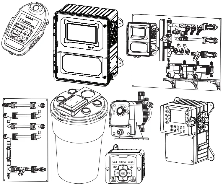
Get the Advantage in Water Treatment Equipment
- Advantage Controls can give you the Advantage in products, knowledge, and support on all of your water treatment equipment needs.
- Cooling Tower Controllers
- Boiler Blow Down Controllers
- Blow Down Valve Packages
- Solenoid Valves
- Water Meters
- Chemical Metering Pumps
- Corrosion Coupon Racks
- Chemical Solution Tanks
- Solid Feed Systems
- Feed Timers
- Filter Equipment
- Glycol Feed Systems
- Pre Fabricated Systems
- Advantage Controls
- 4700 Harold-Abitz Dr.
- Muskogee, OK 74403
- Phone: 19186866211
- Fax: 8886866212
- www.advantagecontrols.com
- E-mail: support@advantagecontrols.com
Documents / Resources
 |
Advantage Controls NANO XL Microprocessor Based Controllers [pdf] Installation Guide NANO XL, NANO XL Microprocessor Based Controllers, Microprocessor Based Controllers, Based Controllers, Controllers |
 |
Advantage Controls NANO XL Microprocessor Based Controllers [pdf] Installation Guide NANO XL, NANO XL Microprocessor Based Controllers, Microprocessor Based Controllers, Based Controllers, Controllers |


