ICUNO-MOD Interface Card Bms Modbus
“
Specifications
- Product Name: BMS Modbus 485
- Compatibility: Compatible with UNO Outdoor Board Series
(UNO/UNOPRO/UNOJR) - Functionality: Integration of air conditioning unit into a
Building Management System - Control Options: Basic BMS Control, Advanced BMS Control
Product Usage Instructions
Installation Procedure
Follow these steps for installing the ICUNO-MOD module:
- Install for Variable Capacity Commercial.
- Install for Classic Series 2 (Reverse Cycle – CRA Models).
- Install for Advance (CRS / CRV / PRV Models).
- BMS Installation Procedure.
- Configure Serial Address and Baud Rate.
- Initialization.
- Configure UNO Board for BMS Control.
- Troubleshooting.
BMS Control
Control the BMS system using the following options:
- Basic BMS Control: Operating unit and Return Air Filter
Notification. - Advanced BMS Control: Operating unit and Return Air Filter
Notification with additional points table. - BMS Monitoring.
- Economy Cycle and Extended Indoor Settings.
FAQ
Q: What should I do before installing the module?
A: Read the manual carefully and ensure compatibility with UNO
Outdoor Board Series.
Q: What is the purpose of BMS Modbus 485?
A: It allows integration of your air conditioning unit into a
Building Management System for better control and monitoring.
Q: How can I troubleshoot issues with the BMS system?
A: Refer to the troubleshooting section in the installation
guide for assistance.
“`
BMS MODBUS 485
Installation and Commissioning Guide
ICUNO-MOD
BMS Modbus is available for compatible units with an UNO Outdoor Board Series* such as:
Variable Capacity
Commercial Classic 2 Advance Aires
(VCC)
· CRV290T · CRV330T · CRV720T · CRV850T · CRV960T · PKV160T-T · PKV180T-T · PKV210T-T · PKV240T-T · PKV290T-T · PKV290T-L/R · PKV330T-T · PKV330T-L/R · PRV15AT · PRV17AT · PKV720T · PKV850T · PKV960T
· CRA100S · CRA130S · CRA130T · CRA150S · CRA150T · CRA170S · CRA170T · CRA200T · CRA230T
· CRV140S · CRV160S · CRV180S · CRV160T · CRV180T · CRV210T · CRV240T · CRV13AS · CRV15AS · CRV17AS · CRV13AT · CRV15AT · CRV17AT
· CRS10AS · CRS13AS · CRS15AS · CRS17AS · CRS13AT · CRS15AT · CRS17AT · CRS20AT · CRS23AT
* UNO Outdoor Board Series refers to UNO/UNOPRO/UNOJR
IMPORTANT NOTE:
Please read this manual carefully before installing the module in the air conditioning unit.
Installation and Commissioning Guide
ICUNO-MOD
Table of Contents
01. Introduction ……………………………………………………………………………………………………………………. 3
01.01. Items to Consider
3
01.02. Safety Instructions
3
01.03. Codes, Regulations and Standards
3
01.04. Waste Electrical and Electronic Equipment Disposal Guidelines
3
02. Parts Included In ICUNO-MOD…………………………………………………………………………………………….4
03. ICUNO-MOD …………………………………………………………………………………………………………………… 5
04. ICUNO-MOD Installation Procedure …………………………………………………………………………………….6
04.01. Installation for Variable Capacity Commercial
6
04.02. Installation for Classic Series 2 (Reverse Cycle – CRA Models)
8
04.03. Installation for Advance (CRS / CRV / PRV Models)
9
04.04. BMS Installation Procedure
10
04.05. BMS Configuration of ICUNO-MOD Card
11
04.05.01. Configure Serial Address
11
04.05.02. Configure Baud Rate and Data Parity
12
04.06. Initialisation
13
04.07. Configure UNO Board for BMS Control
13
04.07.01. Basic BMS Control
14
04.07.02. UNO Board Series Configuration for Basic BMS Control
14
04.07.03. UNO Board Series Configuration for Basic BMS Control + Wall Control
14
04.07.04. Advanced BMS Control
14
04.07.05. UNO Board Series Configuration
15
04.08. Troubleshooting
15
05. BMS Control ……………………………………………………………………………………………………………………18
05.01. Basic BMS Control
18
05.01.01. Operating unit in Basic BMS Control
18
05.01.02. Return Air Filter Notification
18
05.01.03. Basic BMS Points Table
19
05.02. Advanced BMS Control
20
05.02.01. Operating unit in Advanced BMS Control
20
05.02.02. Return Air Filter Notification
20
05.02.03. Advanced BMS Points Table
21
05.03. BMS Monitoring
21
05.04. Economy Cycle and Extended Indoor Settings
24
06. Modbus RS-485 Technical Data…………………………………………………………………………………………. 25
2
Installation and Commissioning Guide ICUNO-MOD
Doc. No. 9590-3013 Ver. 10 240912
Installation and Commissioning Guide
ICUNO-MOD
01. Introduction
CONGRATULATIONS on your purchase of an ActronAir BMS kit. This kit has been designed and engineered to give you total control flexibility for the integration of your ActronAir ducted air conditioner into a central or remote Building Management System. Such integration provides better control and monitoring of your air conditioning system for optimum comfort, efficient operation and energy savings.
The procedures outlined in this guide are provided to correctly and safely install the ActronAir BMS kit to an appropriate ActronAir ducted air conditioning system. Failure to follow these procedures may result in personal injury, damage to the air conditioner, damage to the BMS card or incorrect operation of the air conditioning system. Such failure could render your warranty null and void.
01.01. Items to Consider
· Carefully unpack the ActronAir BMS kit from its packaging.
· Fully check the contents of your kit against the content list upon receiving your shipment. Inspect the components and accessories for any sign of shipping damage. If there is any damage to the contents, contact ActronAir Customer Care Department immediately on: 1300 522 722.
· Make certain that the ActronAir BMS kit is compatible with the ActronAir air conditioning system you plan to install it on.
· Take time to thoroughly read the installation and commissioning instructions before proceeding with the installation.
01.02. Safety Instructions
Safety instructions and warnings provided in this installation manual are non-exhaustive and given as a guide only. Prevailing WH&S regulations must be observed and will take precedence to the safety instructions contained in this manual. Safe work practices and environment must be of paramount importance in the performance of all service procedures.
· Read all instructions in this manual before operating the air conditioning unit. Failure to do so may result in damage to the unit and void your warranty.
· Turn-Off power from mains supply by removing fuse or switching the circuit breaker to the OFF position before performing the installation procedures.
· Follow sound Lock Out and Tag Out procedures to ensure that power supply is not re-energised accidentally.
· Ensure that all safety work procedures and instructions are adhered to at all times in order
to prevent personal injury or damage to the equipment. · Only licensed technicians are allowed to perform the procedures described in this guide. · The ActronAir BMS is for OUTDOOR and Packaged unit use only. Install your BMS away from excessive dust, heat and moisture. · The air conditioning electrical panel and the ActronAir BMSkit contain static sensitive electronic components. Careful handling and correct anti-static procedures must be followed to prevent damage of the equipment. Failure to protect the electronic components from static electricity may cause unrepairable damage, that is NOT COVERED for replacement under Warranty. · The instructions herein refer to work involving sensitive electronic circuitry and components. Please ensure all Instructions are followed accurately so as to prevent damage to these fragile and delicate components. · WH&S rules and regulations must be observed and will take precedence during installation process.
01.03. Codes, Regulations and Standards
The installer and/or contractor assumes responsibility to ensure that ActronAir BMS installation and commissioning comply with the relevant council, state/federal codes, regulations and building code standards. All electrical wiring must be in accordance with current electrical authority regulations and must follow electrical diagrams provided with the unit.
01.04. Waste Electrical and Electronic Equipment Disposal Guidelines
· Do not dispose of the waste electrical and electronic equipment with local council waste. These must be disposed through the council designated hazardous waste collection centre.
· The equipment may contain hazardous substances. Improper or incorrect disposal may have a negative effect on human health and on the environment.
Installation and Commissioning Guide ICUNO-MOD
3
Doc. No. 9590-3013 Ver. 10 240912
Installation and Commissioning Guide
02.Parts Included In ICUNO-MOD
Items
Images
ICUNO-MOD
Quantity
ICUNO-MOD Modbus 485 Card
1
DATA Cable (P/N 26117-1)
1
BMS Connectors
2
PCB Mounts
4
4
Installation and Commissioning Guide ICUNO-MOD
Doc. No. 9590-3013 Ver. 10 240912
Installation and Commissioning Guide
ICUNO-MOD
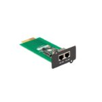
03. ICUNO-MOD
The UNO Modbus RS-485 BMS Card allows the ActronAir Air Conditioners control system to interface with a BMS System. The card allows communication from the UNO Outdoor Board to the customers’ BMS system through the Modbus RTU protocol over RS-485. Each unit on the Modbus RS-485 network has a unique address.
ICUNO-MOD Cable Requirements
Recommended Cable Size: 0.5mm² (7/0.30)
Use two twisted pair shielded data cable to connect the data lines of the RS-485 bus
SW1-SERIAL
SW2-BMS
ADDRESS DIP SETTINGS DIP
SWITCH
SWITCH
OUTDOOR DATA CONNECTOR
BMS IN/OUT CONNECTORS
RESET PUSH BUTTON
STATUS LEDS
SW3-TERMINATION DIP SWITCH
Installation and Commissioning Guide ICUNO-MOD
5
Doc. No. 9590-3013 Ver. 10 240912
Installation and Commissioning Guide
ICUNO-MOD
04.ICUNO-MOD Installation Procedure
04.01. Installation for Variable Capacity Commercial
To install ICUNO-MOD Interface Board into the Outdoor Electrical Panel and to UNO Outdoor Board Step 1. Isolate and fit electrical lockout device and TAG to the main circuit breaker for the system you are working on,
before removing the Electrical Panel Cover. Step 2. Open Electrical Panel Cover. Step 3. Test unit with multimeter to ensure there is no power, before starting installation of the BMS card. Step 4: Use supplied PCB Mounts to mount ICUNO-MOD into correct location.
NOTE: Location will differ between ActronAir systems.
PKV (15kW – 24kW)
PCB MOUNTS
ICUNO-MOD
VCC 85-90 Split and Package.tcw
PKV/CRV (72kW – 96kW) Below image is for PKV850/960T
STAGE 1 ODB
6
ICUNOB-MMS CAORDD
Installation and Commissioning Guide ICUNO-MOD Doc. No. 9590-3013 Ver. 10 240912
Installation and Commissioning Guide
ICUNO-MOD
Step 5. Use the Data Cable provided to connect the BMS card (marked OUTDOOR AUX) 4 Pin socket port to the OUTDOOR BOARD (marked AUX 485) 4 Pin socket port.
AUX 485
UNO OUTDOOR BOARD DUCT RAIL
ICUNO-MOD
OUTDOOR AUX
NOTES:
· Pass the cable through to the Duct Rail when connecting the Outdoor Board from the ICUNO-MOD. · The layout is for illustration purposes only, it will differ between ActronAir systems.
Installation and Commissioning Guide ICUNO-MOD
7
Doc. No. 9590-3013 Ver. 10 240912
Installation and Commissioning Guide
ICUNO-MOD
04.02. Installation for Classic Series 2 (Reverse Cycle – CRA Models)
To install ICUNO-MOD Interface Board into the Outdoor Electrical Panel and to UNOJR Outdoor Board
Step 1. Isolate and fit electrical lockout device and TAG to the main circuit breaker for the system you are working on, before removing the Electrical Panel Cover.
Step 2. Open Electrical Panel Cover.
Step 3. Test unit with multimeter to ensure there is no power, before starting installation of the BMS card.
Step 4. Use supplied PCB Mounts to mount ICUNO-MOD into correct location. NOTE: Location will differ between ActronAir systems.
Step 5. Install BMS ICUNO-MOD as shown below. Step 6. Use the Data Cable provided to connect the BMS card (marked OUTDOOR AUX) 4 Pin socket port to the
OUTDOOR BOARD (marked AUX 485) 4 Pin socket port.
NOTE: The layout is for illustration purposes only, it will differ between ActronAir systems.
Single Phase (10kW – 17kW)
BMS ICUNO-MOD
OUTDOOR BOARD
OUTDOOR AUX
AUX 485
Three Phase (13kW – 23kW)
BMS ICUNO-MOD
OUTDOOR BOARD
OUTDOOR AUX
AUX 485
8
Installation and Commissioning Guide ICUNO-MOD
Doc. No. 9590-3013 Ver. 10 240912
Installation and Commissioning Guide
ICUNO-MOD
04.03. Installation for Advance (CRS / CRV / PRV Models)
To install ICUNO-MOD Interface Board into the Outdoor Electrical Panel and to UNOPRO Outdoor Board Step 1. Isolate and fit electrical lockout device and TAG to the main circuit breaker for the system you are
working on, before removing the Electrical Panel Cover. Step 2. Open Electrical Panel Cover. Step 3. Test unit with multimeter to ensure there is no power, before starting installation of the BMS card. Step 4. Use supplied PCB Mounts to mount ICUNO-MOD into correct location.
NOTE: Location will differ between ActronAir systems. Step 5. Install BMS ICUNO-MOD as shown below. Step 6. Use the Data Cable provided to connect the BMS card (marked OUTDOOR AUX) 4 Pin socket port to the
OUTDOOR BOARD (marked AUX 485) 4 Pin socket port.
NOTE: The layout is for illustration purposes only, it will differ between ActronAir systems.
Single Phase (13kW – 17kW)
BMS ICUNO-MOD OUTDOOR AUX
Three Phase (13kW – 23kW)
BMS ICUNO-MOD OUTDOOR AUX
OUTDOOR BOARD
OUTDOOR BOARD
7245-178-BMS-1Ph.DXF 7245-178-BMS-3Ph.dxf
AUX 485
AUX 485
Installation and Commissioning Guide ICUNO-MOD
9
Doc. No. 9590-3013 Ver. 10 240912
Installation and Commissioning Guide
ICUNO-MOD
04.04. BMS Installation Procedure
INTERMEDIATE BMS DEVICE
INTERMEDIATE BMS DEVICE
LAST BMS DEVICE
CUSTOMER BMS MASTER
SHIELD/DRAIN WIRE
ICUNO-MOD
ICUNO-MOD
ICUNO-MOD
Step 1. Recommended Cable Size: 0.5mm² (7/0.30)
· Use 0.5mm² (7/0.30) two twisted pair shielded data cable to connect to the A,B,COM and SCRN terminals of either of the two BMS connectors.
· One of the twisted pair cables must be used to connect the A terminals of each of the Modbus RS-485 devices on the network. The other cable, from the same twisted pair, must be used to connect all the B terminals.
· The other twisted pair should be joined together and connected to the COM terminal. · Connect the Screen wires to the SCRN terminal of the connector. Note: COM and SCRN must be connected to ICUNO-MOD. On the BMS control end, ensure COM and SCRN are connected to the same earth as the BMS controller. The RS485 on the ICUNOMOD is isolated to prevent ground loops.
Step 2. If another Modbus RS-485 device is to be connected on the same network, then use the other BMS Connector to daisy chain additional devices.
Step 3. If the unit, wherein the BMS device is connected, is at the start or the end of the Modbus RS-485 network, the SW3 DIP 1 (120R ) switch must be turned on.
Note: It is required to earth the shield wire of the data cable at the BMS Master end.
BMS IN/OUT
A B COM SCRN
INTERMEDIATE BMS DEVICE
SW3 TERMINATION
DIP SWITCH
FIRST OR LAST BMS DEVICE
SW3 TERMINATION
DIP SWITCH
10
Installation and Commissioning Guide ICUNO-MOD
Doc. No. 9590-3013 Ver. 10 240912
Installation and Commissioning Guide
ICUNO-MOD
04.05. BMS Configuration of ICUNO-MOD Card
Consult project system designer (BMS engineer or similar role) for the correct Modbus RS-485 configuration for this unit.
Use the DIP switches on the BMS Card to configure the Modbus parameters. New BMS configuration will take effect when the BMS card initializes, either by the RESET button or power cycle.
04.05.01. Configure Serial Address
SW1-SERIAL ADDRESS DIP SWITCH
NOTE: The Serial Address is a number that uniquely identifies a device on the local RS-485 network. If two units have the same Serial Address, identification errors will be generated. There will be no indication on the BMS card of any error, however the BMS system will not communicate with these devices. Series Address can be any number between 1 – 247.
Modbus RS-485 Serial address can be configured using SW1 SERIAL ADDRESS DIP switch.
Serial Address
1
Value 1
SW1-SERIAL ADDRESS DIP Switch
1
2
3
4
5
6
7
8
OFF OFF OFF OFF OFF OFF OFF ON
2
2
OFF OFF OFF OFF OFF OFF ON OFF
3
2 + 1
OFF OFF OFF OFF OFF OFF ON ON
…
245
128 + 64 + 32 + 16 + 4 + 1
ON ON ON ON OFF ON OFF ON
246
128 + 64 + 32 + 16 + 4 + 2
ON ON ON ON OFF ON ON OFF
247
128 + 64 + 32 + 16 + 4 + 2 + 1 ON ON ON ON OFF ON ON ON
128 64 32 16
8
4
2
1
DIP Switch Value
Serial Address 3 shown: 128 64 32 16 8 4 2 1 ON
OFF 1 2 3 4 5 6 7 8
Installation and Commissioning Guide ICUNO-MOD
11
Doc. No. 9590-3013 Ver. 10 240912
Installation and Commissioning Guide
ICUNO-MOD
04.05.02. Configure Baud Rate and Data Parity
SW2-BMS SETTINGS DIP SWITCH
Modbus RS-485 Baud Rate and Data Parity can be configured by setting SW2 as per the table below.
Function
Data Parity
Baud Rate
NONE EVEN 9600 19200 38400 57600 76800 115200
SW2 – DIP Switch
1
2
3
4
ON
OFF
OFF OFF OFF
OFF OFF ON
OFF ON OFF
OFF ON ON
ON OFF OFF
ON OFF ON
NOTE: The Data Parity and Baud Rate must be the same for all the devices connected on the local RS-485 network, otherwise the exchange of data will generate communication errors. If the BMS card has the incorrect data parity or baud rate, then the Status 2 LED (white) will FLASH slowly (once every 2 seconds). See Section 04.08 for BMS Troubleshooting.
12
Installation and Commissioning Guide ICUNO-MOD
Doc. No. 9590-3013 Ver. 10 240912
Installation and Commissioning Guide
ICUNO-MOD
04.06. Initialisation
Step 1. Once all installation steps have been completed, power can be turned ON from mains supply by removing electrical lockout device and switching isolator switch to the On position at the Main Supply at the Outdoor Unit.
Step 2. BMS card will take 60 seconds to initialize with the Air Conditioning system and the BMS configuration. While the BMS card is initializing, the Status 2 LED (white) will FLASH (once every 2 seconds). The BMS card will not accept any BMS commands during this time.
Step 3. After 60 seconds the Amber Status LED should be ON, indicating a stable connection to the ActronAir Air Conditioning System.
Step 4. If the Client BMS system is active and sending commands to this device, then the White Status LED should also be ON. NOTE: See Section 04.08 for BMS Troubleshooting.
Step 5. If any BMS configurations need to be changed, then make the applicable changes outlined in Section 04, and press the RESET button on the BMS Card.
RESET PUSH BUTTON
Step 6. BMS card will take 60 seconds to initialize with the new BMS configuration NOTE: New BMS configurations will only take affect once the BMS card has been reset
04.07. Configure UNO Board for BMS Control
There are two modes for BMS operation (Basic BMS and Advanced BMS), the project system designer (BMS engineer or similar role) should understand the BMS operations and decide which is suitable for their application.
Installation and Commissioning Guide ICUNO-MOD
13
Doc. No. 9590-3013 Ver. 10 240912
Installation and Commissioning Guide
ICUNO-MOD
04.07.01. Basic BMS Control
Basic BMS Control is useful for applications looking for a relatively simple BMS solution. This BMS setup allows you to operate the ActronAir AC unit in the same way our wall controls do.
The system operating logic is controlled by the ActronAir on-board controls, providing a wide range of functions and features. This removes the need to have to re-write the HVAC or air conditioning logic into your BMS controller, as the system will take care of it for you.
With this setup, you can use the BMS to: Turn the system on/off Adjust room setpoint temperature Change the mode of operation: Auto/Cool/Heat/Fan Only Change the supply fan settings: Low/Medium/High/Auto Set the supply air filter notification timer Open and Close zones
The ActronAir AC system may be configured to operate in Basic BMS Control, or Basic BMS Control with a Wall Control. When operating in Basic BMS Control with a Wall Control, all settings changes from the BMS and Wall Control will be synchronized across the entire system.
Additional information for controlling the unit in Basic BMS Control can be found in Section 05.01.
04.07.02. UNO Board Series Configuration for Basic BMS Control
To configure the ActronAir AC system for Basic BMS Control, follow the procedure using the 7-segment display on the UNO Board below:
Step 1. Press the MENU button to navigate to SEt (Settings), press the ENTER button to enter sub-menu.
Step 2. Press the MENU button to navigate to CtrS (Control Source), press the ENTER button to enter sub-menu.
Step 3. Press the MENU button to navigate to 2 (Basic BMS), press the ENTER button to accept.
Step 4. Press the BACK button twice to return to Main Screen.
04.07.03. UNO Board Series Configuration for Basic BMS Control + Wall Control
To configure the ActronAir AC system for Basic BMS Control + Wall Control, follow the procedure using the 7-segment display on the UNO Board below:
Step 1. Press the MENU button to navigate to SEt (Settings), press the ENTER button to enter sub-menu.
Step 2. Press the MENU button to navigate to CtrS (Control Source), press the ENTER button to enter sub-menu.
Step 3. Press the MENU button to navigate to 3 (Basic BMS + Wall Control), press the ENTER button to accept.
Step 4. Press the BACK button twice to return to Main Screen.
04.07.04. Advanced BMS Control
Advanced BMS control is better suited to more complex or bespoke scenarios. This BMS setup is ideal for those applications where the air conditioning needs to link with other products, or if you require customized functions not included in the existing software and logic in the on-board controls.
Even with the highly customizable level of control, the ActronAir software ensures that the safety logics of operations are still in place to ensure that the ActronAir system will stop to prevent any problems from occurring.
With this setup, you can use the BMS to: Turn the system on/off Control compressor capacity Set supply fan speed Control Heat/Cool (reversing valve on/off) Set the supply air filter notification timer Open and Close zones
14
Installation and Commissioning Guide ICUNO-MOD
Doc. No. 9590-3013 Ver. 10 240912
Installation and Commissioning Guide
ICUNO-MOD
A Wall Control can not be used if the ActronAir AC system is configured for Advanced BMS Control. Additional information for controlling the unit in Advanced BMS Control can be found in Section 05.02.
04.07.05. UNO Board Series Configuration
To configure the ActronAir AC system for Advanced BMS Control, follow the procedure using the 7-segment display on the UNO Board below: Step 1. Press the MENU button to navigate to SEt (Settings), press the ENTER button to enter sub-menu. Step 2. Press the MENU button to navigate to CtrS (Control Source), press the ENTER button to enter sub-menu, Step 3. Press the MENU button to navigate to 4 (Advanced BMS), press the ENTER button to accept. Step 4. Press the BACK button twice to return to Main Screen.
04.08. Troubleshooting
The LEDs on the board indicate the status of the BMS Card. Use the troubleshooting table on the following page to resolve any issues.
STATUS LEDS
BMS CARD STATUS Power to BMS Card Successful communication with A/C unit Successful communication with BMS controller
LED INDICATION Red Power LED ON Amber Status LED ON White Status LED ON
Installation and Commissioning Guide ICUNO-MOD
15
Doc. No. 9590-3013 Ver. 10 240912
Installation and Commissioning Guide
ICUNO-MOD
Troubleshooting Table:
Symptom
Power LED (Red) is OFF
Probable Cause
No Power to BMS Card
BMS Card is Faulty
Status 1 LED (Amber) Flashing
AC Tx (Blue) LED OFF Status 1 LED (Amber) Flashing
AC Rx (Blue) LED OFF
BMS Card is Faulty
No Communication with UNO Outdoor
Board
Status 2 LED (White) OFF BMS Rx (Amber) OFF
Status 2 LED (White) OFF
No Communication from BMS Master
Incorrect Serial Address
BMS Rx (Amber) Flashing
Status 2 LED (White) Incorrect Baud Rate
Flashing Slowly
or Data Parity
(once every 2 seconds)
Status 2 LED (White) Flashing Rapidly (twice every second)
BMS Card has detected RS-485 data corruption
(CRC Cyclic Redundancy Check
has failed)
Suggested Resolution · Confirm Power to Outdoor Unit and power on the UNO Outdoor Board. · Check interconnect cable connection between UNO Outdoor Board and BMS
Card. See Section 04 for correct installation procedure. · Check continuity of interconnect cable.
· If there is power to the UNO Outdoor Board, the interconnect cable is secure, then the BMS card may be faulty.
· Replace the BMS Card.
· Replace the BMS Card.
· Check the interconnect cable connection between UNO Outdoor Board and BMS Card. One or more cables/connections may be faulty.
· If COM3 LED on the UNO Outdoor Board is flashing and all data harness connections are secure, then there may be a fault with the UNO Outdoor Board or BMS Card.
· Replace the BMS Card. · If this fails to resolve the issue, replace the UNO Outdoor Board. · Confirm that BMS Master is currently operating. · Check BMS RS-485 connections from the BMS Master to this BMS Card.
· Confirm correct Serial Address Parity as per your installed BMS unit setup and change DIP switch settings as required. See Section 04.05.01 for Serial Address DIP switch settings.
· Reset the BMS Card following any DIP Switch changes on the board, by pressing the RESET button.
· Confirm correct Baud Rate and Data Parity as per your installed BMS network setup and change DIP switch settings as required.
· See Section 04.05.02 for Baud Rate and Parity DIP switch settings. · Reset the BMS Card following any DIP Switch changes on the board, by pressing
the RESET button.
· Check for any sources of noise or interruptions on the BMS RS-485 Network. · Ensure correct RS-485 grounding and shielding throughout BMS RS-485
Network. · Ensure correct cable specifications throughout BMS RS-485 Network.
16
Installation and Commissioning Guide ICUNO-MOD
Doc. No. 9590-3013 Ver. 10 240912
Installation and Commissioning Guide
ICUNO-MOD
Symptom
Probable Cause
Suggested Resolution
Air Conditioning Unit won’t operate from BMS
Air Conditioner Fault · An Air Conditioner fault may prevent the unit from operating from a BMS
Preventing AC from
command.
operating
· Or the UNO Outdoor Board may be incorrectly setup for BMS Control.
OR
UNO Outdoor Board not configured correctly for BMS Control
· From the unit, check the UNO Outdoor Board 7-segment display for any Unit Fault Error Codes
· Consult the Air Conditioner unit’s troubleshooting guide to resolve the fault. · Confirm that the UNO Outdoor Board is setup for the correct BMS Control
Mode as per your installed BMS network setup · See Section 05 for instructions on configuring UNO Outdoor Board for BMS
Control.
· From the BMS Controller, ensure that you are able to read data from the correct BMS Registers, and that there are no address base issues.
· Try reading from Modbus Analogue Register 405 for BMS Card Software Version · If Modbus Register 405 reads a 0, then try read from Modbus Register 406
instead. If this returns a non-zero value, then plus one offset will need to be added to all Modbus registers. · Check for any Air Conditioner operation faults by reading the Alarm Output from Modbus Analogue Register 503. If this register is 1, then the unit will not operate. · Check BMS Card to A/C unit communications by reading from Modbus Analogue Register 909. If this register reads a 1, then the BMS Card is not connected to the A/C unit correctly. · Inspect UNO Outdoor Board and BMS Card for faults · Check the unit fault error code by reading from Modbus Analogue Register 900. · Consult the Air Conditioner unit’s troubleshooting guide to resolve the fault. · Once all faults are resolved, Modbus Analogue Register 503 should be cleared, indicating that the unit is no longer in a fault condition. · Confirm that the UNO Outdoor Board is setup for the correct BMS Control Mode by reading the BMS Control Mode from Modbus Analogue Register 505. · If operating in Basic BMS Control, then Modbus Analogue Register 505 should read 1. · If operating in Advanced BMS Control, then Modbus Analogue Register 505 should read 2. · See Section 05 for instructions on configuring UNO Outdoor Board for BMS Control.
If the above steps fail to fix the problem. Contact ActronAir Technical Support on 1800 119 229 for further assistance.
Installation and Commissioning Guide ICUNO-MOD
17
Doc. No. 9590-3013 Ver. 10 240912
Installation and Commissioning Guide
ICUNO-MOD
05. BMS Control
This section of the document provides a guide to using the ActronAir BMS Table. This section explores the Modbus registers relevant to each BMS Operation Mode, their usage and meaning to control the various units.See “BMS Configuration of ICUNO-MOD Card” section for instructions on configuring your unit for BMS Control.
Additional information for status and setting of BMS can be found in “BMS Monitoring” section.
05.01. Basic BMS Control
If the Air Conditioning unit is setup for Basic BMS Control, then Modbus Analogue Register 505 should read a 1. If Register 505 reads any other value, then the unit has not been correctly setup to run in Basic BMS Control. See “Configure UNO Board for BMS Control” section for appropriate configuration of BMS Control.
05.01.01. Operating unit in Basic BMS Control
The unit can be operated following the steps below:
Step
Operation
1.
Set the Fan Mode (Modbus Analog 4)
1 Low
2 Medium
3 High
2. Set Supply Fan Controls (Modbus Analog 105)
0 Standard
1 Continuous Fan
3. Set the Mode of Operation (Modbus Analog 101)
1 Heat Only
2 Cool Only
3 Auto Changeover
4 Fan Only
4. Set the Master Setpoint Temperature (Modbus Analog 102). Minimum and
Maximum setpoint limits can be read in the BMS table in Section 05.01.03
230 = 23.0°C
267 = 26.7°C
NOTE: Ensure that at least one zone is turned On whenever the system is On.
05.01.02. Return Air Filter Notification
The Return Air filter can be monitored following the steps below:
Step
Operation
1.
Set the Indoor Filter Timer to the required time* (Modbus Analog 7).
See installation and commissioning guide for more details.
2.
Read the Indoor Filter Run Hours (Modbus Analog 509) for the number of hours
the indoor fan has run since the last time the filter was cleaned.
3.
The Air Filter Alarm (Modbus Analog 506) will be set when the run hours equal the
filter timer.
4.
To reset the alarm, access the unit and clear the air filter, then reset the Filter
Notification (Modbus Analog 6)
0 = Off
1 = Reset
5.
Once the Filter Notification has been reset, then the Indoor Filter Run Hours will
reset to 0, and the Air Filter Alarm will clear.
6.
To disable the Air Filter Notification function, set the Indoor Filter Timer to -1
(Modbus Analog 7)
*Setting the Indoor Filter timer will reset the Indoor Filter run hours and clear any Air Filter Alarm on the system.
18
Installation and Commissioning Guide ICUNO-MOD
Doc. No. 9590-3013 Ver. 10 240912
Basic Unit Control
Installation and Commissioning Guide
ICUNO-MOD
05.01.03. Basic BMS Points Table
Description
VCC
Turns the AC On/OFF via BMS (0=Off, 1=On)
l
Set the Supply Fan Mode** (1=Low, 2=Medium, 3=High, 4=Auto)
l
Reset Air Filter Notification (0=Off, 1=Reset)
l
Set Air Filter Notification Timer (Hr)
l
Mode of Operation (1=Heat Only,
2=Cool Only, 3=Auto Changeover,
l
4=Fan Only)
Set Master Setpoint Temperature (0.1°C)
l
Set Supply Fan Controls (0 = Standard, 1 = Continuous)
l
Set Turbo Mode (0= Off, 1 = On)
l
Set Quiet Mode (0= Off, 1 = On)
l
Alarm Output (0=Off, 1=On)
l
BMS Demand Mode
(0=No BMS, 1=Basic BMS,
l
2=Advanced BMS)
Air Filter Notification (0=Off, 1=On)
l
Air Filter Run Timer (Hr)
l
Actual System Running Capacity (0.1%)
l
Room Temperature (0.1°C)
l
Set zone 1 (0=Off, 1=On)
Set zone 2 (0=Off, 1 =On)
Set zone 3 (0=Off, 1=On)
Set zone 4 (0=Off, 1=On)
Set zone 5 (0=Off, 1=On)
Set zone 6 (0=Off, 1=On)
Set zone 7 (0=Off, 1=On)
Set zone 8 (0=Off, 1=On)
Advance
l
l
l l
l
l
l l l l
l
l l l l l l l l l l l l
Aires
Classic 2
Modbus Register
Read/ Write
l
l
1
R/W
l
l
4
R/W
l
l
6
R/W
l
l
7
R/W
l
l
101 R/W
l
l
102 R/W
l
l
105 R/W
l
109 R/W
l
110 R/W
l
l
503
R
l
l
505
R
l
l
506
R
l
l
509
R
l
l
801
R
l
l
851
R
l
l
5001 R/W
l
l
5002 R/W
l
l
5003 R/W
l
l 5004 R/W
l
l
5005 R/W
l
l
5006 R/W
l
l
5007 R/W
l
l
5008 R/W
UoM Min Max
1
0
1
1
1
4
1
0
1
1Hr 0Hr 10000Hr
1
1
4
0.1°C 16.0°C 30.0°C
1
0
1
1
0
1
1
0
1
1
0
1
1
0
2
1
0
1
1Hr 0Hr 10000Hr
0.1% 0.0% 100.0%
0.1°C -99.9°C 99.9°C
1
0
1
1
0
1
1
0
1
1
0
1
1
0
1
1
0
1
1
0
1
1
0
1
**Fan speed PWM limits can be set from the ActronAir units service menu. Consult the Air Conditioner units installation guide for more information. If system has been configured as a single speed indoor fan Register 4 – Supply fan mode can only be set to MEDIUM speed. “4=Auto” is only available on Advance Units and after a self-learn is successful from the wall controller.
All registers are Type: Analog. Unsigned or Signed 16-bit integers / U16 or I16.
Unit Status
Zone Control
Installation and Commissioning Guide ICUNO-MOD
19
Doc. No. 9590-3013 Ver. 10 240912
Installation and Commissioning Guide
ICUNO-MOD
05.02. Advanced BMS Control
If the Air Conditioning unit is setup for Advanced BMS Demand Mode, then Modbus Register 505 should read a 2. If Register 505 reads any other value, then the unit has not been correctly setup to run in Advanced BMS Control. See Section 04.07.04 for instructions on configuring your unit for Advanced BMS Control.
05.02.01. Operating unit in Advanced BMS Control
The unit can be operated following the steps below:
Step
Operation
Set the Supply Fan Speed Demand
1.
(Modbus Analog 203)*
350 = 35.0%
Set the Compressor Capacity Demand
2.
(Modbus Analog 201)*
800 = 80.0%
Set the Heat Request (Modbus Analog 202)
3.
0 Cool Mode
1 Heat Mode
4.
Turn the AC unit OFF/ON (Modbus Analog 1)**
0 Off
1 – On
* ActronAir software ensures that system operational safety is retained by maintaining minimum and maximum safe compressor demand and fan speed demand. Consult the Air Conditioner units installation guide for safe operating limits.
** The AC unit must be turned ON to operate the Supply Fan and Compressor.
NOTE: Ensure that at least one zone is turned On whenever the system is On.
05.02.02. Return Air Filter Notification
The Return Air filter can be monitored following the steps below:
Step
Operation
1.
Set the Indoor Filter Timer to the required time* (Modbus Analog 7).
See installation and commissioning guide for more details.
2.
Read the Indoor Filter Run Hours (Modbus Analog 509) for the number of hours
the indoor fan has run since the last time the filter was cleaned.
3.
The Air Filter Alarm (Modbus Analog 506) will be set when the run hours equal the
filter timer.
4.
To reset the alarm, access the unit and clear the air filter, then reset the Filter
Notification
(Modbus Analog 6)
0 = Off
1 = Reset
5.
Once the Filter Notification has been reset, then the Indoor Filter Run Hours will
reset to 0, and the Air Filter Alarm will clear.
6.
To disable the Air Filter Notification function, set the Indoor Filter Timer to -1
(Modbus Analog 7)
*Setting the Indoor Filter timer will reset the Indoor Filter run hours and clear and Air Filter Alarm on the system.
20
Installation and Commissioning Guide ICUNO-MOD
Doc. No. 9590-3013 Ver. 10 240912
Installation and Commissioning Guide
ICUNO-MOD
05.02.03. Advanced BMS Points Table
Unit Control
Description
Turns the AC On/OFF via BMS (0=Off, 1=On) Reset Air Filter Notification (0=Off, 1=Reset) Set Air Filter Notification Timer (Hr) Set System Capacity Demand (0.1%)1,2 Set Heat Request (0=Off, 1=On) Set Supply Fan Speed Demand (0.1%) 1 Set Damper Output (0.1V) Alarm Output (0=Off, 1=On)
VCC
Advance
Aires
Classic 2
Modbus Register
Read/ Write
UoM
Min
Max
l
l
l
l
1
R/W 1 0
1
l
l
l
l
l
l
l
l
l
l
l
l
l
l
l
l
l
l
l
l
l
l
l
l
l
l
l
l
6
R/W 1 0
1
7
R/W 1Hr 0Hr 10000Hr
201 R/W 0.1% 0.0% 100.0%
202 R/W 1 0
1
203 R/W 0.1% 0.0% 100.0%
204 R/W 0.1 V 0 V 10.0 V
503
R
1
0
1
Unit Status
BMS Demand Mode (0=No BMS, 1=Basic BMS, 2=Advanced BMS)
l
l
l
l
505
R
1
0
2
Air Filter Notification (0=Off, 1=On)
l
l
l
l
506
R
1
0
1
Air Filter Run Timer (Hr)
l
l
l
l
509
R 1Hr 0Hr 10000Hr
Actual System Running Capacity (0.1%) l
l
l
l
801
R 0.1% 0.0% 100.0%
Set zone 1 (0=Off, 1=On)
l
l
l
5001 R/W 1
0
1
Set zone 2 (0=Off, 1=On)
l
l
l
5002 R/W 1
0
1
Set zone 3 (0=Off, 1=On)
l
l
l
5003 R/W 1
0
1
Set zone 4 (0=Off, 1=On)
l
l
l
5004 R/W 1
0
1
Set zone 5 (0=Off, 1=On)
l
l
l
5005 R/W 1
0
1
Set zone 6 (0=Off, 1=On)
l
l
l
5006 R/W 1
0
1
Set zone 7 (0=Off, 1=On)
l
l
l
5007 R/W 1
0
1
Set zone 8 (0=Off, 1=On)
l
l
l
5008 R/W 1
0
1
Zone Control
*Applicable to Platinum and Advance Series 1. ActronAir software ensures that system operational safety is retained by maintaining minimum and maximum safe compressor
demand and fan speed demand. Consult the Air Conditioner unit’s installation guide for safe operating limits. 2. Actual system running capacity (Modbus Analog 801) and Indoor Fan1 Speed (Modbus Analog 1311) will reflect the Set System
Capacity Demand and Supply Fan Speed Demand respectively 3. All registers are Type: Analog. Unsigned or Signed 16-bit integers / U16 or I16.
05.03. BMS Monitoring
Provides the data about unit operation like refrigerant low/high pressures, temperature sensor values, Electronic Expansion Valve (EEV) opening, fan speeds, zone status and digital inputs/outputs.
Installation and Commissioning Guide ICUNO-MOD
21
Doc. No. 9590-3013 Ver. 10 240912
Unit Status and Conditions
Installation and Commissioning Guide
ICUNO-MOD
BMS Monitoring Points Table
Description
BMS Card Software Version
Alarm Output (0=Off, 1=On) BMS Demand Mode (0=No BMS, 1=Basic BMS, 2=Advanced BMS) Air Filter Notification (0=Off, 1=On) Air Filter Run Timer (Hr) Actual System Running Capacity (0.1%) Demand Response (0 = No DRM, 1 = DRM1, 2 = DRM2, 3 = DRM3) Remote On/Off (0=Low, 1=High) Room Temperature (0.1°C) Outside Air Temperature (0.1°C) Current Error Code (Consult the Air Conditioner unit’s installation guide for Error Code descriptions) Error History Log, 1 Error ago Error History Log, 2 Errors ago Error History Log, 3 Errors ago Error History Log, 4 Errors ago Error History Log, 5 Errors ago No Communications with Indoor Unit (0=No Error, 1=Off line) No Communications with Outdoor Unit (0=No Error, 1=Off line) Room Temperature Sensor Status (0 = OK, 1 = Error) Outside Air Temperature Sensor Status (0 = OK, 1 = Error) Outdoor Unit 1 Model Outdoor Unit 1 Software Version Compressor 1 Type
VCC / Advance
Aires
Classic 2
Modbus Register
Read/ Write
UoM
l
l
l
405
R
1
l
l
l
503
R
1
l
l
l
505
R
1
l
l
l
506
R
1
l
l
l
509
R
1Hr
l
l
l
801
R
0.1%
Min Max
0
65535
0
1
0
2
0
1
0Hr 10000Hr
0.0% 100.0%
l
l
l
804
R
1
0
4
l
l
l
805
R
1
0
1
l
l
l
851
R
0.1°C -99.9°C 99.9°C
l
l
852
R
0.1°C -99.9°C 99.9°C
l
l
l
900
R
1
0
100
l
l
l
901
R
1
0
100
l
l
l
902
R
1
0
100
l
l
l
903
R
1
0
100
l
l
l
904
R
1
0
100
l
l
l
905
R
1
0
100
l
l
l
906
R
1
0
1
l
l
l
909
R
1
0
1
l
l
l
951
R
1
0
1
l
l
952
R
1
0
1
l
l
l
1001
R
1
0
65535
l
l
l
1002
R
1
0
65535
l
l
l
1004
R
1
0
100
Unit Faults
Model
22
Installation and Commissioning Guide ICUNO-MOD
Doc. No. 9590-3013 Ver. 10 240912
Compressor 1 Status
Installation and Commissioning Guide
ICUNO-MOD
Description
VCC / Advance
Compressor 1 running status (0=Off, 1=On)
l
Compressor 1 Heating (0=Off, 1=On)
l
Compressor 1 Demand (0.1%)
l
Compressor 1 Speed (0.1%)
l
Compressor 1 Unit Defrosting (0 = Off, 1 = Defrosting)
l
Compressor 1 Suction Pressure (kPa)
l
Compressor 1 Discharge Pressure (kPa)
l
Compressor 1 Suction Temperature (0.1°C)
l
Compressor 1 Discharge Temperature (0.1°C)
l
Compressor 1 Suction Superheat (0.1°K)
l
Compressor 1 Suction Superheat Target (0.1°K)
l
Compressor 1 LP Switch Trip (0=Off, 1=Trip) l
Compressor 1 HP Switch Trip (0=Off, 1=Trip) l
Compressor 1 HP or LP Lockout (0=Off, 1=Lockout)
l
Outdoor Coil 1 Temperature (0.1°C)
l
Outdoor Coil 1 Fan Speed Setting (0=Off, 1=Low, 2=Med, 3=High)
l
Indoor Coil Temperature (0.1°C)
l
Indoor Coil 1 Fan 1 Speed (0.1%)
l
Indoor Coil 1 Fan 1 Speed (RPM)
l
Compressor 1 EEV position (0.1%)
l
Compressor 1 Discharge Temp High (0=Off, 1=On)
l
Compressor 1 LP Status (0 = OK, 1 = Error)
l
Compressor 1 HP Status (0 = OK, 1 = Error)
l
Compressor 1 Suction Temperature Status (0 = OK, 1 = Error)
l
Compressor 1 Discharge Temperature Status (0 = OK, 1 = Error)
l
Outdoor Coil 1 Temperature Status (0 = OK, 1 = Error)
l
Indoor Coil Temperature Status (0 = OK, 1 = Error)
l
Aires
l l l l l l l l l l l l l l l l l l l l l
l
l
l
l
l
l
Classic 2
Modbus Register
Read/ Write
l
1101
R
l
1102
R
l
1104
R
1105
R
l
1107
R
1111
R
1112
R
1113
R
1114
R
1115
R
1117
R
l
1118
R
l
1119
R
l
1122
R
l
1201
R
l
1215
R
l
1301
R
l
1311
R
l
1312
R
1401
R
1502
R
1503
R
1504
R
1505
R
1506
R
l
1507
R
l
1508
R
UoM Min Max
1
0
1
1
0
1
0.1% 0.0% 100.0%
0.1% 0.0% 100.0%
1
0
1
1kPa 0kPa 6000kPa 1kPa 0kPa 6000kPa 0.1°C -999.9°C 999.9°C
0.1°C -999.9°C 999.9°C
0.1°K -99.9°K 99.9°K
0.1°K -99.9°K 99.9°K
1
0
1
1
0
1
1
0
1
0.1°C -99.9°C 99.9°C
1
0
3
0.1°C 0.1% 1RPM 0.1%
-99.9°C 99.9°C 0.0% 100.0% 0RPM 9999RPM 0.0% 100.0%
1
0
1
1
0
1
1
0
1
1
0
1
1
0
1
1
0
1
1
0
1
EEV ID Coil OD Coil
Sensor
Installation and Commissioning Guide ICUNO-MOD
23
Doc. No. 9590-3013 Ver. 10 240912
Room Temperature Sensors
Installation and Commissioning Guide
ICUNO-MOD
Description Wall Control 1 Temperature (0.1°C)
VCC / Advance
Aires
Classic 2
Modbus Register
Read/ Write
UoM
Min
Max
l
l
l
6001
R
0.1°C -99.9°C 99.9°C
Wall Control 2 Temperature (0.1°C)
l
l
l
6002
R
0.1°C -99.9°C 99.9°C
Wall Control 3 Temperature (0.1°C)
l
l
l
6003
R
0.1°C -99.9°C 99.9°C
Auxiliary Sensor 1 Temperature (0.1°C)
l
l
l
6011
R
0.1°C -99.9°C 99.9°C
Auxiliary Sensor 2 Temperature (0.1°C)
l
l
l
6012
R
0.1°C -99.9°C 99.9°C
Auxiliary Sensor 3 Temperature (0.1°C)
l**
l
l
6013
R
0.1°C -99.9°C -99.9°C
** For residential systems only.
All registers are Type: Analog. Unsigned or Signed 16-bit integers / U16 or I16.
Economiser
05.04. Economy Cycle and Extended Indoor Settings
Description
Enable Outside Air Damper (0=Off, 1=On) Enable Economiser (0=Off, 1=On) Enable Humidity Control Humidity Sensor Configuration (0=Outdoor, 1=Outdoor & Indoor) Moisture Control Config (0=Moisture, 1=Enthalpy) Enable CO Control (0=Off, 1=On) Economiser Temperature Difference (0.1°C) Economiser Outside Min Temperature (0.1°C) Economiser Outside Max Temperature (0.1°C) Economiser Minimum Damper Economiser Maximum Damper Economiser Outside Max Humidity (.1 %) Economiser Outside Max Moisture (0.1 x g/kg) Economiser Outside Max Dew Point (0.1 x kJ/kg) Economiser Outside Max Enthalpy (0.1 x kJ/kg) Economiser Enthalpy Delta (0.1°C) Economiser CO Low Level Economiser CO High Level Economiser CO Minimum Damper Economiser CO Maximum Damper
VCC / Modbus Advance Register
l
340
l
341
l
342
l
343
l
344
l
345
l
351
l
352
l
353
l
354
l
355
l
356
l
357
l
358
l
359
l
360
l
361
l
362
l
363
l
364
Read/ Write R/W R/W R/W
R/W
R/W R/W R/W R/W R/W R/W R/W R/W R/W R/W R/W R/W R/W R/W R/W R/W
UoM Min
Max
1
0
1
1
0
1
1
0
1
1
0
1
1
0
1
1
0
1
0.1°C
0
10.0°C
0.1°C
0
22.5°C
0.1°C
0
26.0°C
0.1 V
0 V
10.0 V
0.1 V
0 V
10.0 V
0.1% 0.0% 100.0%
0.1% 0.0 g/kg 100.0 g/kg
0.1% 0.0 kJ/kg 100.0 kJ/kg
0.1% 0.0 kJ/kg 100.0 kJ/kg
0.1°C
0
10.0°C
PPM
0
1000
PPM
0
1000
0.1 V
0 V
10.0 V
0.1 V
0 V
10.0 V
24
Installation and Commissioning Guide ICUNO-MOD
Doc. No. 9590-3013 Ver. 10 240912
Installation and Commissioning Guide
ICUNO-MOD
Extended Indoor Settings
Description
VCC / Modbus Read/ Advance Register Write
UoM
Target Airflow
l
307 R/W L/s
Enable Volumetric Airflow
l
308 R/W L/s
Indoor Pressure Filter Level Warning
l
310 R/W
Pa
Reduced Airflow Speed (0.1%)
l
316 R/W 0.1%
Enable Desuperheater (0=Off, 1=On)
l
320 R/W
1
Desuperheater Inlet Temperature Cutout (0.1 °C)
l
321 R/W 0.1°C
Enable Overflow Sensor (0=Off, 1=On)
l
322 R/W
1
Desuperheater Active (0=Off, 1=On)
l
620
R
1
De-superheater Water Inlet Temperature (0.1 °C)
l
621
R
0.1°C
Enable Overflow Sensor (0=Off, 1=On)
l
622
R
1
Reduced Airflow Active (0=Off, 1=On)
l
705
R
0.1%
Indoor Airflow
l
860
R
L/s
Indoor Static Pressure
l
861
R
Pa
Measured CO Level
l
862
R
PPM
Min
0 0 0 0.0% 0 0 0 0 -99.9°C 0 0.0% 0 0 0
Max
6000 6000 6000 100.0%
1 26.0°C
1 1 -99.9°C 1 100.0% 6000 6000 1000
06.Modbus RS-485 Technical Data
Device Type Baud Rates Data Parity Unit Load Device Address Range Protocol Electrical Interface Cable Type Recommended Wire Size Connector type Supported function codes
Broadcast Maximum Network Cable Length Standard Data Format
Slave 9600 (Default), 19200, 38400, 76800, 115200 Even (Default), None 1/32 1 247 Modbus RTU RS-485, 4 Wire (2 pair) Twisted Pair Shielded Cable 0.5mm² (7/0.30) Screw terminals 03 Read Holding Registers 06 Write Single Register 16 Write Multiple Registers Yes 1000 meters (@9600 baud rate) Modbus over serial line v1.0
8-N-1 (Eight data bits, No parity bits and One stop bit)
Installation and Commissioning Guide ICUNO-MOD
25
Doc. No. 9590-3013 Ver. 10 240912
THIS PAGE WAS INTENTIONALLY LEFT BLANK
THIS PAGE WAS INTENTIONALLY LEFT BLANK
actronair.com.au 1300 522 722
Refrigerant Trading Authorisation No.: AU06394
©Copyright 2019 Actron Engineering Pty Limited ABN 34 002767240. ®Registered Trade Marks of Actron Engineering Pty Limited.
28
Documents / Resources
 |
ActronAir ICUNO-MOD Interface Card Bms Modbus [pdf] User Guide ICUNO-MOD Interface Card Bms Modbus, ICUNO-MOD, Interface Card Bms Modbus, Card Bms Modbus, Bms Modbus, Modbus |