
microBOGEY RF Transmitter Installation Guide
PART NO.
microBOGEY-4T4
microBOGEY-8T4

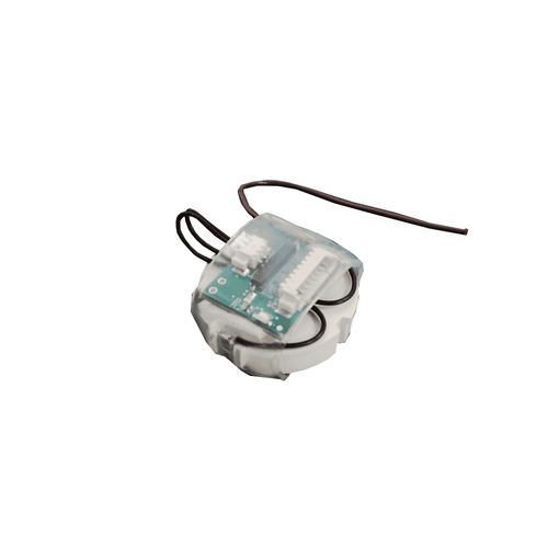
microBOGEY works out of the box
Connect switch inputs, Then deploy.
When an input is operated the MICROBOGEY will transmit an RF signal and the LED Flashes
Pairing microBOGEY to a Receiver
microBOGEY is compatible with other RF Solutions Receivers (at the same Frequency). Each module is factory programmed with a unique identity. A Receiver “learns” the each individual microBOGEY input. Please follow the Receiver instructions for pairing.
Change Feature Settings
The following features can be changed by briefly presenting a magnet next to the Reed Switch.

To update / change the Feature, briefly present a magnet to the Reed Switch and follow the instructions for each of the features as shown below

Safety Information
Carefully read the following safety information before proceeding with installation, operation, or maintenance of RF Solutions product. Failure to follow these warnings could result in death or serious injury.
- This radio system must not be used in areas where there is a risk of explosion.
- Only qualified personnel should be permitted to access the transmitter and operate the equipment.
- Always follow operating information as well as all applicable safety procedures and requirements.
- You must satisfy the age requirements in your country for operating the equipment.
- Store in a safe place.
- Keep a clear view of the work area at all time before using, check it is safe to do so Before maintenance intervention on any remote controlled equipment
- Do not open the receiver enclosure unless you are qualified.
- Disconnect all electrical power from the equipment.
- Check the enclosure and cable for damage regularly, do not use if there is evidence of damage
Battery Precautions
- Risk of explosion if battery is replaced with a battery of an incorrect type.
- Do not short-circuit, disassemble, deform or heat batteries.
- Never attempt to charge a visibly damaged or frozen battery.
- Do not use or charge the battery if it appears to be leaking, deformed or damaged in any way.
- Immediately discontinue use of the battery if, while using, charging, or storing the battery, the battery emits an unusual smell, feels hot, changes color, changes shape, or appears abnormal in any other way.
- Keep batteries out of reach of small children. Should a child swallow a battery, consult a physician immediately.
Acknowledgement Request
(Menu 2)
When activated the MICROBOGEY requests an acknowledgement back from the receiver.
MICROBOGEY will retry upto 4 times until an acknowledgement is received, after that it will flash its LED at high speed to indicate no acknowledgement received.
Note: If you are using a MICROBOGEY to operate multiple receivers at the same time (one to many) we recommend turning OFF the acknowledgement to avoid RF contention with the Ack

Momentary or Latching Switch Input
(Menu 3)
Momentary Switch Input (Continuous RF Transmit) MICROBOGEY continuously transmits “INPUT CLOSED”.
If the Acknowledgment request is ON the receiver will reply after each RF transmission burst.
This is suited to momentary “push to make” Switch types.
Latching Switch Input (State Change Transmit) MICROBOGEY transmits when the input is OPENED or CLOSED i.e. a state change only.

Transmit Power
(menu 4)

High Power (+20dBm) is capable of upto 4KM*
Low Power (+10dBm) is capable of upto 1KM*
Please note that as well as transmit power, range depends on Antenna, type and position: Receiver sensitivity, Antenna type and position!
Using High Power uses more battery power.
For Example:
Using CR2450 battery (supplied),
@ High Power will achieve 400K Transmissions
@ Low Power will achieve 1,800K Transmissions
(shelf Life of the CR2450 is 10 years)
External Antenna Option
The antenna provided can be replaced with an external antenna if required. The wire antenna can be cut and and external antenna connected to the UFL Connector.
RF Solutions offer several lengths of Coax Cable assembly CBA-UFLSMA which plugs directly onto the UFL Antenna connector on the MICROBOGEY and provides a panel mount SMA connector.

There is a large selection of suitable Antenna with varying form factor all which have a matching SMA connector.

Replacement Interface Cables
The Battery Cable Assembly and the Switch Input cables are available as spare parts

Replacing the Battery
1. Unscrew the battery case lid.
2. Replace the battery type CR2450 Ensure you have the “+ve” to the top

Simplified Declaration of Conformity (RED)
Hereby, RF Solutions Limited declares that the radio equipment type defined within this document is in compliance with Directive 2014/53/EU. The full text of the EU declaration of conformity is available at the following internet address: www.rfsolutions.co.uk
RF Solutions Ltd. Recycling Notice
Meets the following EC Directives:
DO NOT
Discard with normal waste, please recycle.
ROHS Directive 2011/65/EU and amendment 2015/863/EU
Specifies certain limits for hazardous substances.
WEEE Directive 2012/19/EU
Waste electrical & electronic equipment. This product must be disposed of through a licensed WEEE collection point. RF Solutions Ltd., fulfils its WEEE obligations by membership of an approved compliance scheme, environment agency registration number: WEE/JB0104WV.

Waste Batteries and Accumulators
Directive 2006/66/EC
Where batteries are fitted, before recycling the product, the batteries must be removed and disposed of at a licensed collection point.
RF Solutions battery producer number BPRN00060.
Disclaimer:
Whilst the information in this document is believed to be correct at the time of issue, RF Solutions Ltd does not accept any liability whatsoever for its accuracy, adequacy or completeness. No express or implied warranty or representation is given relating to the information contained in this document. RF Solutions Ltd reserves the right to make changes and improvements to the product(s) described herein without notice. Buyers and other users should determine for themselves the suitability of any such infor-mation or products for their own particular requirements or specification(s). RF Solutions Ltd shall not be liable for any loss or damage caused as a result of user’s own determination of how to deploy or use R F Solutions Ltd’s products. Use of RF Solutions Ltd products or components in life support and/or safety applications is not author-ised except with express written approval. No licences are created, implicitly or otherwise, under any of RF Solutions Ltd’s intellectual property rights. Liability for loss or damage resulting or caused by reliance on the information contained herein or from the use of the product (including liability resulting from negligence or where RF Solutions Ltd was aware of the possibility of such loss or damage arising) is excluded. This will not operate to limit or restrict RF Solutions Ltd’s liability for death or personal injury resulting from its negligence.
RF Solutions Ltd
William Alexander House, William way, Burgess Hill, West Sussex, RH15 SAG
Sales: +44 (0)1444 227900 | Support: +44 (0)1444 227909
Read More About This Manual & Download PDF:
Documents / Resources
 |
RF microBOGEY RF Transmitter [pdf] Installation Guide microBOGEY-4T4, microBOGEY-8T4, microBOGEY RF Transmitter, RF Transmitter, Transmitter |


