LS GRL-D22C Programmable Logic Controller
Specifications
- Model Number: C/N 10310000312
- Product Name: Programmable Logic Controller Smart I/O Rnet
- Compatible Models: GRL-D22C, D24C, DT4C/C1, GRL-TR2C/C1,TR4C/C1, RY2C
- Dimensions: 100mm
Product Usage Instructions
Installation:
- Ensure the power is off before installation.
- Mount the PLC in a suitable location using appropriate mounting hardware.
- Connect input and output devices to the designated ports.
Programming:
- Use the provided software to program the logic controller based on your requirements.
- Test the program thoroughly before deploying it for operation.
Maintenance:
- Regularly check for any loose connections or signs of wear and tear.
- Keep the device clean and free from dust accumulation.
Frequently Asked Questions
- Q: How do I reset the PLC to factory settings?
- A: To reset the PLC to factory settings, refer to the user manual for specific instructions on initiating a factory reset procedure.
- Q: Can I expand the I/O capacity of the PLC?
- A: Yes, you can expand the I/O capacity of the PLC by adding compatible expansion modules. Refer to the product documentation for information on supported expansion options.
Product Information
Smart I/O Rnet GRL-D22C,D24C,DT4C/C1GRL-TR2C/C1,TR4C/C1,RY2C
This installation guide provides simple function information or PLC control. Please read carefully this data sheet and manuals before using products. Especially read precautions and then handle the products properly.
Safety Precautions
 WARNING WARNING indicates a potentially hazardous situation which, if not avoided, could result in death or serious injury
CAUTION indicates a potentially hazardous situation which, if not avoided, may result in minor or moderate injury. It may also be used to alert against unsafe practices
WARNING
- Do not contact the terminals while the power is applied.
- Be sure there are no foreign metallic matters.
- Do not manipulate the battery(charge, disassemble, hitting, short, soldering).
CAUTION
- Be sure to check the rated voltage and terminal arrangement before wiring
- When wiring, tighten the screw of the terminal block with the specified torque range
- Do not install flammable things on the surroundings
- Do not use the PLC in an environment of direct vibration
- Except forexpert service staff, do not disassemble or fix or modify the product
- Use the PLC in an environment that meets the general specifications contained in this datasheet.
- Be sure that the external load does not exceed the rating of the output module.
- When disposing of PLC and battery, treat it as industrial waste.
- I/O signal or communication line shall be wired at least 100mm away from a high-voltage cable or power line.
Operating Environment
To install, observe the below conditions.
| No | Item | Specification | Standard | ||||
| 1 | Ambient temp. | 0 ~ 55℃ | – | ||||
| 2 | Storage temp. | -25 ~ 70℃ | – | ||||
| 3 | Ambient humidity | 5 ~ 95%RH, non-condensing | – | ||||
| 4 | Storage humidity | 5 ~ 95%RH, non-condensing | – | ||||
|
5 |
Vibration Resistance |
Occasional vibration | – | – | |||
| Frequency | Acceleration |
IEC 61131-2 |
|||||
| 5≤f<8.4㎐ | – | 3.5mm | 10 times in each direction
for X, Y, Z |
||||
| 8.4≤f≤150㎐ | 9.8㎨(1g) | – | |||||
| Continuous vibration | |||||||
| Frequency | Frequency | Frequency | |||||
| 5≤f<8.4㎐ | – | 1.75mm | |||||
| 8.4≤f≤150㎐ | 4.9㎨(0.5g) | – | |||||
Accessories and Cable Specifications
- Check 5pin connector attached in the product.
- When using Rnet communication, twisted pair cable shall be used with consideration of communication distance and speed.
- Item: Low Capacitance LAN Interface Cable
- Type: LIREV-AMESB
- Size : 1P X 22AWG(7/0.254)
- Manufacturer: LS Cable the maker of equivalent material specifications below
- Electrical characteristics
| Items | Unit | Characteristics | Condition |
| Conductor Resistance | Ω/km | 59 or less | 25℃ |
| Withstanding Voltage (DC) | V/1min | 500V, 1Min. | In air |
| Insulation Resistance | MΩ-km | 1,000 or more | 25℃ |
| Capacity | Pf/M | 45 or less | 1kHz |
| Characteristic Impedance | Ω | 120±12 | 10MHz |
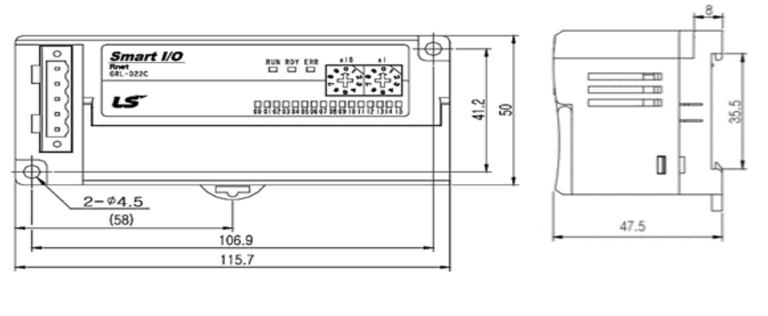
Dimension (mm)
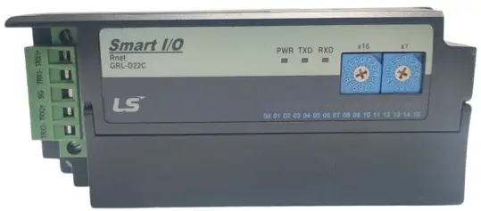
This is front part of the Module. Refer to each name when operating the system. For more information, refer to user’s manual.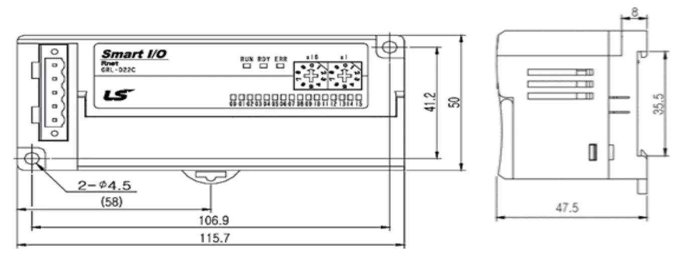
Performance Specifications
- This is the performance specifications of the Module. Refer to each name when driving the system. For more information, refer to user manual.
| Item | GRL-D2xC | GRL-DT4C/C1 | GRL-TRxC/C1 | GRL-RY2C |
| Rated Input Current | 5mA | – | – | |
| Rated load voltage | – | DC24V | DC24V/AC220V,
2A/Point, 5A/COM |
|
| Max load | – | 0.5A/Point, 3A/COM | DC 110V, AC 250V
1,200times/hour |
|
| ON Voltage | DC 19V or above | Minimum load voltage/current DC 5V/1mA | ||
| OFF Voltage | DC 6V or less | |||
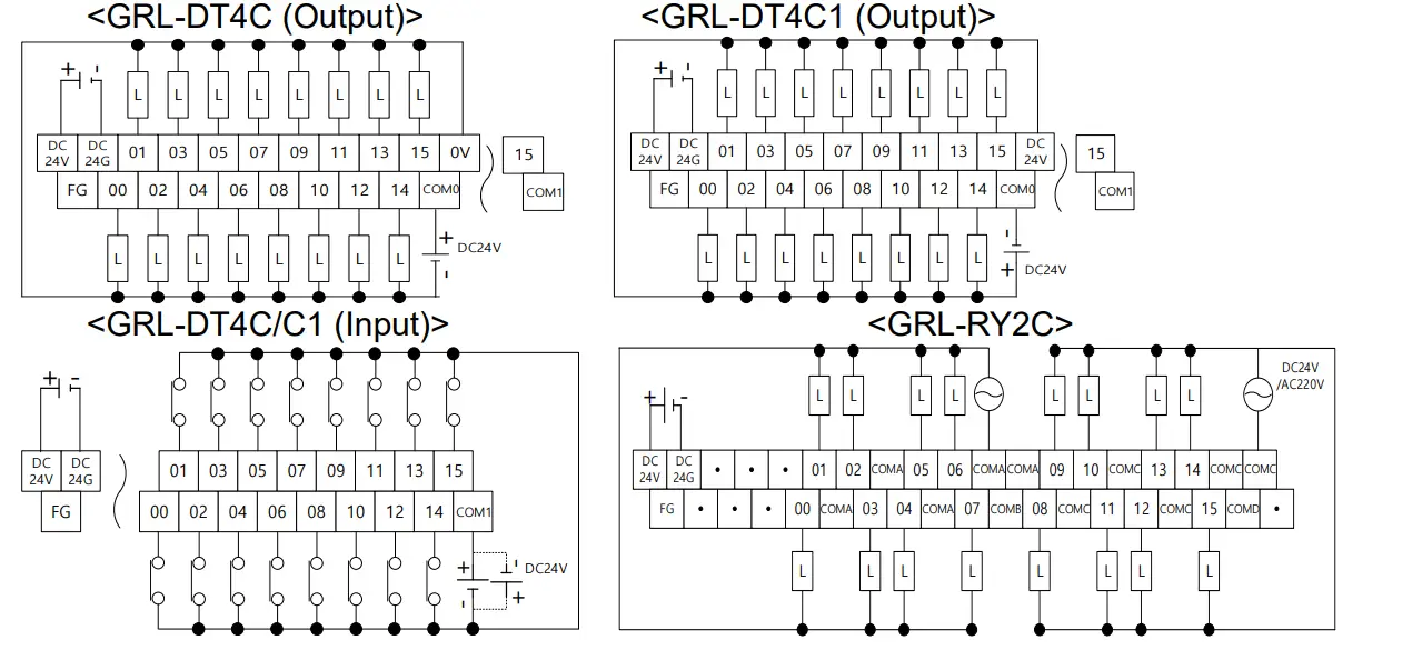
Terminal Block Layout for I/O Wiring
This is terminal block layout for I/O wiring. Refer to each name when driving the system. For more information, refer to user manual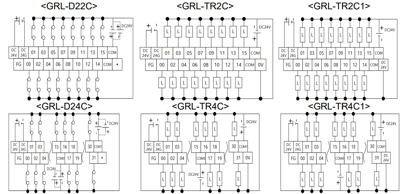
Wiring
Wiring for Communication
- XGT Rnet ↔ Smart I/O 5pin
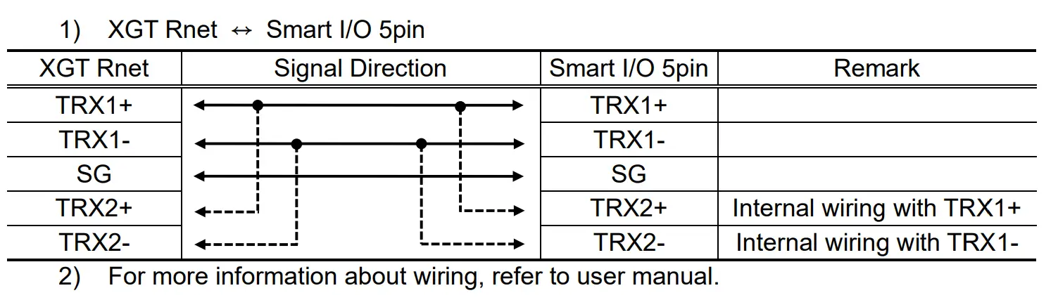
- For more information about wiring, refer to user manual.
Warranty
- The warranty period is 36 months from the date of manufacture.
- The initial diagnosis of faults should be conducted by the user. However, upon request, LS ELECTRIC or its representative(s) can undertake this task for a fee. If the cause of the fault is found to be the responsibility of LS ELECTRIC, this service will be free of charge.
- Exclusions from warranty
- Replacement of consumable and life-limited parts (e.g. relays, fuses, capacitors, batteries, LCDs, etc.)
- Failures or damages caused by improper conditions or handling outside those specified in the user manual
- Failures caused by external factors unrelated to the product
- Failures caused by modifications without LS ELECTRIC’s consent
- Use of the product in unintended ways
- Failures that cannot be predicted/solved by current scientific technology at the time of manufacture
- Failures due to external factors such as fire, abnormal voltage, or natural disasters
- Other cases for which LS ELECTRIC is not responsible
- For detailed warranty information, please refer to the user’s manual.
- The content of the installation guide is subject to change without notice for product performance improvement.
LS ELECTRIC Co., Ltd. www.ls-electric.com 10310000312 V4.5 (2024.6)
- E-mail: automation@ls-electric.com
- Headquarters/Seoul Office Tel: 82-2-2034-4033,4888,4703
- LS ELECTRIC Shanghai Office (China) Tel: 86-21-5237-9977
- LS ELECTRIC (Wuxi) Co., Ltd. (Wuxi, China) Tel: 86-510-6851-6666
- LS-ELECTRIC Vietnam Co., Ltd. (Hanoi, Vietnam) Tel: 84-93-631-4099
- LS ELECTRIC Middle East FZE (Dubai, U.A.E.) Tel: 971-4-886-5360
- LS ELECTRIC Europe B.V. (Hoofddorf, Netherlands) Tel: 31-20-654-1424
- LS ELECTRIC Japan Co., Ltd. (Tokyo, Japan) Tel: 81-3-6268-8241
- LS ELECTRIC America Inc. (Chicago, USA) Tel: 1-800-891-2941
- Factory: 56, Samseong 4-gil, Mokcheon-eup, Dongnam-gu, Cheonan-si, Chungcheongnamdo, 31226, Korea

Documents / Resources
 |
LS GRL-D22C Programmable Logic Controller [pdf] Installation Guide GRL-D22C Programmable Logic Controller, GRL-D22C, Programmable Logic Controller, Logic Controller, Controller |