FS 800G OSFP Transceiver Module
Product Information
Specifications
- Product: 800G OSFP & QSFP-DD Transceiver Module
- Version: V1.0.2502A
Overview
Statement
This guide describes general handling measures and precautions when handling OSFP/QSFP-DD transceiver module to ensure that the risk of damage is reduced during processing
Module Apperance Overview
OSFP Transceiver Module
An optical OSFP transceiver module with MPO-16/APC connector is shown in Figure 1.
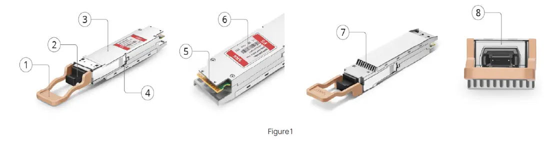
| 1 | Pull tab | 2 | Dust cap | 3 | Module body | 4 | Unlock structure |
| 5 | Golden Fingers | 6 | Tag | 7 | Finned Top | 8 | MPO-16/APC |
An optical OSFP transceiver module with Dual MPO-12/APC connector is shown in Figure 2. 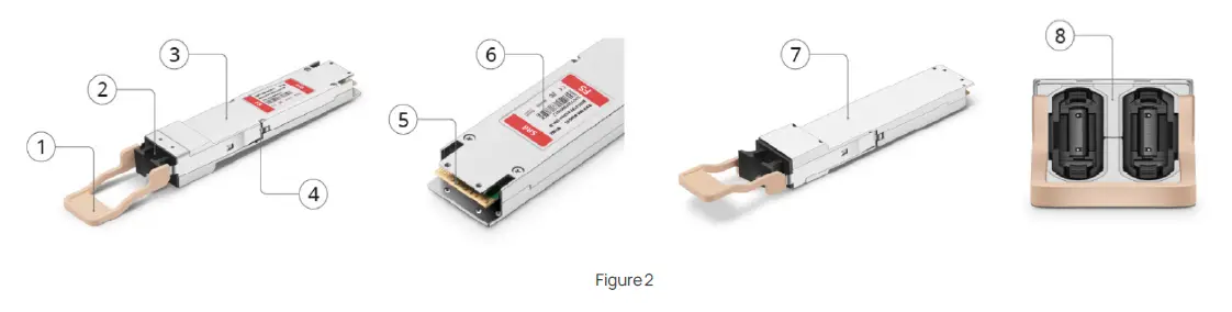
| 1 | Pull tab | 2 | Dust cap | 3 | Module body | 4 | Unlock structure |
| 5 | Golden Fingers | 6 | Tag | 7 | Flat Top | 8 | Dual MPO-12/APC |
An optical OSFP transceiver module with Dual-duplex LC/UPC connector is shown in Figure 3. 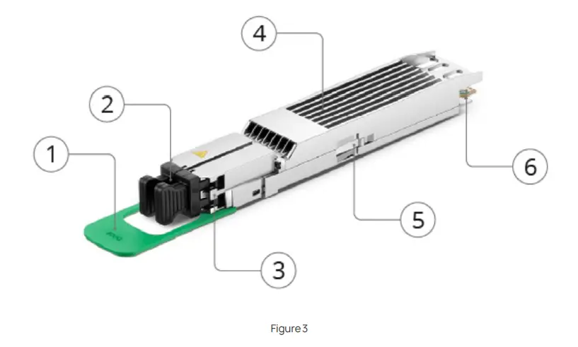
| 1 | Pull tab | 2 | Dust cap | 3 | Dual-duplex LC/UPC |
| 4 | Finned Top | 5 | Unlock structure | 6 | Golden Fingers |
QSFP-DD Transceiver Module
An optical QSFP-DD transceiver module with MPO-16/APC connector is shown in Figure 4. 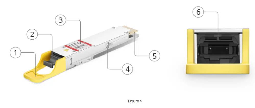
| 1 | Pull tab | 2 | Dust cap | 3 | Tag |
| 4 | Unlock structure | 5 | Golden Fingers | 6 | MPO-16/APC |
An optical QSFP-DD transceiver module with Dual MPO-12/APC connector is shown in Figure 5. 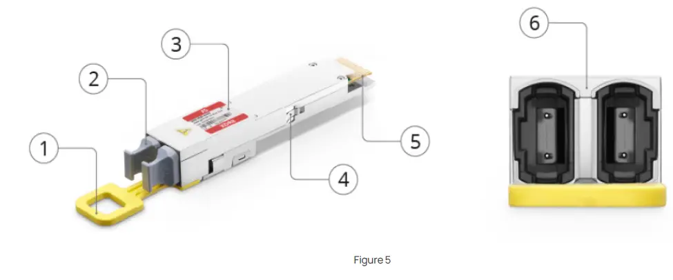
| 1 | Pull tab | 2 | Dust cap | 3 | Tag |
| 4 | Unlock structure | 5 | Golden Fingers | 6 | Dual MPO-12/APC |
An optical QSFP-DD transceiver module with Dual-duplex LC/UPC connector is shown in Figure 6. 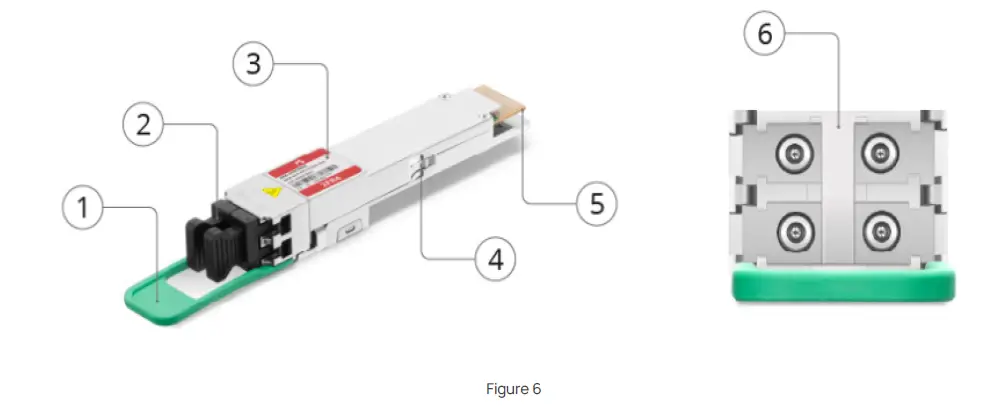
| 1 | Pull tab | 2 | Dust cap | 3 | Tag |
| 4 | Unlock structure | 5 | Golden Fingers | 6 | Dual-duplex LC/UPC |
Safety
Precautions
 Moisture-proof caution
 Do not disassemble or modify
 Wear anti-static gloves
 Avoid viewing fiber optic port
 Qualified personnel only for installation or replacement
- The theoretical insertion and removal times of the transceiver modules are generally 500 to 2000 times. Removing and inserting the OSFP/QSFP-DD transceiver module will shorten its service life. Therefore, do not insert or remove the OSFP/QSFP-DD transceiver module unless necessary.
- Disconnect all fiber patch cables before removing or installing the OSFP/QSFP-DD transceiver module . Do not install or remove OSFP/QSFP-DD transceiver modules with fiber patch cables, as this may cause potential damage to the fibers or modules, limiting transmission performance.
- After removing the optical fibers, protect them by inserting a clean dust cover on the pluggable module. Make sure to clean the optical surface of the cable before plugging it back into the optical port of the other OSFP/QSFP-DD transceiver module. Avoid dust and other contaminants entering the optical port of the OSFP/QSFP-DD transceiver module, as the optics will not function properly when obstructed by dust.
- Transceiver modules are sensitive to static electricity. Therefore, ensure that you use an ESD wrist strap or a similar grounding device or ESD gloves when installing and removing the OSFP/QSFP-DD transceiver module.
- When two transceiver modules are connected, ensure that both OSFP/QSFP-DD transceiver module are of the same model.
ESD precautions [1]
- Transceiver modules are susceptible to ESD (electrostatic discharge), which can damage sensitive integrated circuits. The person removing the module should wear an ESD wrist strap that is connected to the ground potential. Workstations and workstations should be ESD protected and connected to a common ground point.
- Caution: The transceiver module is an electrostatic sensitive device. Always use an ESD wrist strap or similar separate grounding device when handling transceiver modules or contact modules.
Operating Temperature of Transceiver Module
In order to ensure the long-term stable operation of the transceiver module, it is important to ensure that it works in the right temperature range. In addition, periodically monitoring the operating status of the transceiver module and ensuring good heat dissipation can effectively extend the service life of the transceiver module.
The operating temperature range of the transceiver module is usually specified by the manufacturer and is generally divided into the following two categories:
- Commercial grade: 0°C to 70°C
- Industrial grade: -40°C to 85°
The effects of a high or low temperature on an transceiver module are as follows:
- The effect of excessive temperature
Signal attenuation: Excessively high temperatures can increase signal attenuation, resulting in degraded optical transmission quality and even data transmission errors.
Component aging: High temperatures will accelerate the aging of electronic components inside transceiver modules and shorten the service life of modules.
Increased risk of failure: The transmitting and receiving parts of the transceiver module may fail or even be permanently damaged due to excessive temperatures. - The effect of too low a temperature
Startup issues: If the temperature is too low, the transceiver module may not start or work properly, especially in applications outside the industrial-grade temperature range.
Unstable optical power: Low temperature may lead to the instability of the optical power of the laser, affecting data transmission
When using, make sure that the transceiver module works within its specified temperature range, otherwise it may cause performance degradation or even damage to the module. The following parameters affect the operating box temperature and its surface temperature of the transceiver module, including the ambient temperature of the platform operating environment, airflow, cage and heat sink design, all of which affect the enclosure temperature of the module. If a module needs to be physically extracted from a port, it should be done while the module is within a comfortable range that can be handled.
The operating temperature of the module’s enclosure is typically about 10 to 15 degrees higher than the ambient temperature. Transceiver modules operating at an ambient temperature of 45°C can easily reach 60°C or higher, making the metal transceiver module body higher than the standard recommended. The module is designed to effectively dissipate heat through heat conduction from the host platform cage and the passenger radiator, provided there is sufficient airflow.
Installing QSFP-DD and OSFP Transceiver Modules
Installing/Replacing Transceiver Modules [2] To install an QSFP-DD/OSFP transceiver module, please follow these steps:
- Step 1 Attach an ESD-preventive wrist strap to your wrist and to the ESD ground connector or a bare metal surface on your chassis.
- Step 2 Remove the QSFP-DD/OSFP transceiver module from its protective packaging.
- Step 3 Check the label on the QSFP-DD/OSFP transceiver module body to verify that you have the correct model for your network.
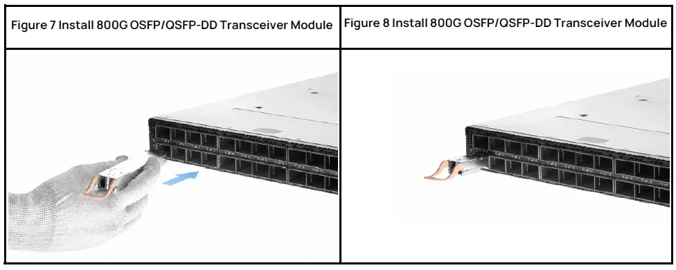
- Step 4 Hold the transceiver module so that the identifier label is at the bottom. Align the transceiver module with the front of the platform port, and carefully slide the transceiver module into the socket until it touches the electrical connector of the socket. On some platforms, the OSFP/QSFP-DD cage is mounted up and down, in which case the identifier tag must be at the top. (As shown in Figures 7 to 8)
- Step 5 Press the front of the transceiver module firmly with your thumb so that the transceiver module is completely secured in the OSFP/QSFP-DD cage (Caution: If the latch is not fully engaged, you may accidentally disconnect the OSFP/QSFP-DD transceiver module).
 Step 6 Do not remove the dust plug until you are ready to connect the fiber.
- Step 7 Always use a fiber connector cleaner to clean the fiber connector surface, which should be done every time the fiber is plugged into the module’s optical outlet.
Installing/Replacing Fiber Optic Patch Cords
- Step 1 Check that the labels on the patch cords are correct, clear and tidy. If the label is not easily recognized, you will need to recreate and apply the label to avoid errors when connecting the cables.
- Step 2 Check the fiber connection status. Before disassembling it, make sure that the fiber patch cord connection is in normal condition and that there is no bending or other damage.
- Step 3 When disassembling the optical fiber patch cord (taking the MTP patch cord replacement as an example)wear anti-static gloves, use the index finger and thumb of one hand to fix the left and right sides of the OSFP/QSFP-DD transceiver module, and use the index finger and thumb of the other hand to fix the upper and lower sides of the MTP connector, make sure that the MTP patch cord is horizontal (no tilt angle), and then carefully pull out the MTP patch cord with slight force (avoid pulling the optical fiber). Make sure to remove the connector gradually to prevent excessive stress on the fiber).
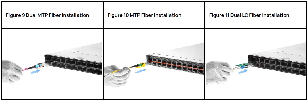 Step 4 After removing the fiber patch cables, remove the dustproof plug from the new fiber patch cables. Use your index finger and thumb to secure the upper and lower sides of the new fiber patch cables connector. Connect the keys on the connector body to the keyway on the transceiver module. Insert the fiber patch cables into the module horizontally (at a non-tilting Angle) until the locking device clicks.
(Before making sure the connector is clean). (As shown in Figures 9 to 11)- Step 5 When the link is fully established, the LED will glow solid green.
- Step 6 After replacing the fiber patch cord: Store the old fiber patch cord in anti-static
Removing QSFP-DD and QSFP Transceiver Modules
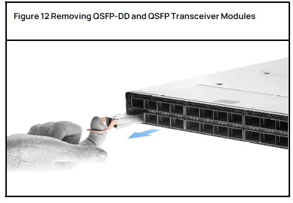
Caution: The pluggable OSFP/QSFP-DD transceiver module is designed with a pull-tab release mechanism.
To remove the transceiver module, use the pull tab and follow these steps:
- Step 1 Tie the ESD wrist strap to yourself and place the ESD wrist strap on the chassis or rack.
- Step 2 For transceiver modules, disconnect the optical connector from the module. Fiber optic connectors should be kept clean.
- Step 3 Optical transceiver with pull tab lock:
- Immediately install the dust plug into the optical hole of the transceiver module.
- Grasp the label with your finger and gently pull to release the transceiver module from the socket.
- Slide the transceiver out of the socket and hold only the pull tabs without touching the pluggable metal surface.
- Step 4 Place the transceiver module on an ESD workbench or work area, and then insert the transceiver module into an ESD bag.
Cleaning and Maintenance
End face Treatment and Cleaning [4]
- Transceiver modules can be damaged by exposure to electrical surges and overvoltage events. Please note the conditions that limit exposure to the absolute maximum rating. Follow the normal operation precautions of ESD sensitive equipment.
- The transceiver is equipped with dust caps on both the electrical and optical ports. When no fiber is connected, the cover on the optical port should always be in place. Fiber optic connectors have a recessed connector surface that is exposed when there are no fibers or covers.
- Important tip 1: Keep the dust caps on the optical fibers and transceiver modules.
- Important tip 2: Before inserting the optical fiber, clean the end face of the transceiver module and the end face of the fiber patch cables to prevent contamination.
- Dust caps ensure that optical components are kept clean during transport. Standard cleaning tools and methods should be used during installation and maintenance. Do not use liquids.
- Important tip 3: 80% of the transceiver module link problems are related to dirty optical fiber connectors.
Maintain Fiber Patch Cables [5] To maintain fiber patch cords:
- When unplugging an optical fiber from an transceiver module, place rubber helmet at the end of the transceiver module and optical fiber.
- Secure the fiber to avoid stress on the connector. When connecting the fiber to the transceiver module, be sure to secure the fiber so that the fiber does not support its weight when it hangs on the floor. Never allow the fiber to hang freely from the connector.
- Do not bend the fiber beyond its minimum bend radius. Bending an optical fiber beyond its minimum bend radius can damage the fiber and cause problems that are difficult to diagnose.
- Frequent plugging and unplugging of optical fibers in and out of optical instruments can damage the instrument and make repairs costly. Connect a short fiber extension cord to the optical device. Any wear and tear due to frequent plugging and unplugging is absorbed by the short fiber extension cord, which is easier to replace and less expensive than an instrument.
- Keep your fiber optic connection clean. Tiny deposits of oil and dust in the ducts of transceiver modules or fiberoptic connectors can cause light loss, reduced signal power, and can lead to intermittent problems with optical connections.
- To clean the transceiver channels, use appropriate fiber cleaning equipment, such as the ATC-NS-125 Fiber Adapter Cleaning Stick (part number #190742). Follow the instructions in the cleaning kit you are using.
- After cleaning the transceiver module, make sure that the connector tip of the optical fiber is clean. Use only approved alcohol-free fiber cleaning kits, such as Cletop-S® fiber Cleaner. Follow the instructions in the cleaning kit you are using.
Product Warranty
FS guarantees to our customers that we will return the goods free of charge within 30 days from the date you receive them due to any damage or malfunction caused by our processes. For transceiver modules, if there is any quality problem within 1 year, we also provide replacement service (note that the above return service does not include customized products).
Warranty:
All transceivers are covered by a 5-year limited warranty against defects in materials or workmanship. For more details on the warranty, please check the https://www.fs.com/policies/warranty.html
Returns:
If you want to return a product, you can find information on how to return it at https://www.fs.com/policies/day_return_policy.html
Security and Compliance
- In accordance with Part 15 of the FCC Rules, this device has been tested and demonstrated to meet the restrictions for Class B digital devices. These restrictions are intended to provide reasonable protection against harmful disturbances in residential installations. This device generates, uses and may radiate radio frequency energy, which, if not installed and used according to instructions, may cause harmful interference with radio communications.
- Hereby, FS.COM declares that this product is in compliance with Directive 2014/30/EU. A copy of the EU declaration of conformity is available at the following internet address: www.fs.com/company/quality_control.html
- Class 1 Laser compliant.
- To comply with the above laser safety standards, FS products should be used in conjunction with FS products manufactured by our approved suppliers and certified Category 1 products.
Handling of Common Problems
Plugging and Unplugging Transceiver Modules
Transceiver Module Mount Mroblems
The bayonet of the transceiver module may be improperly connected, mismatched, or improperly inserted and removed. To solve these problems, we need to consider hardware, connectors, protocols and other aspects. The following are some suggested solutions for the bayonet problem of transceiver modules:
- Find the unlock position of the module, the OSFP/QSFP-DD module is generally on the left and right sides of the module.
- Use tweezers or stainless steel cards to insert between the bayonet module and the switch cage, and then pull out the bayonet module gradually with horizontal force.
- Be careful not to scratch the module or damage the switch port during this process.
Transceiver Module Installation Problems
Check carefully before installation
- Check the golden finger of the transceiver module to keep the end face bright and clean.
- Check whether ports on the device are damaged.
- Check the port interface of the transceiver module. Make sure there are no obvious damage issues.
- Check whether the pin of the fiber is damaged.
Module installation problems may involve many aspects, including physical connections, connectors, and device compatibility. Here are some possible common problems and ways to deal with them:
Transceiver module installation issues:
- Problem: The transceiver module is not properly inserted into the device slot, resulting in damage to the device port/transceiver module.
- Solution: When plugging in the device, the transceiver must be plugged in tightly and the straps must be in place. Make sure the transceiver plugs are properly aligned and nudge into the slot. Hearing a “click” sound indicates that the plug-in is correct and ensures that the module locking mechanism is working properly. Otherwise, when the equipment is subjected to vibration and shock, it can easily be interrupted or loosened.
MTP fiber Installation Issues:
- Problem: The MTP patch cord is not properly inserted into the transceiver module, resulting in damage to the module port/MTP patch cord.
- Solution: Check whether the transceiver module and the patch cord can be matched before use, for example, the OSFP-SR8-800G transceiver module needs to be paired with the MTP12 Type B polarity OM4 APC patch cord, when installing the MTP patch cord, you need to use the index finger and thumb to fix the upper and lower sides of the MTP connector, the keys on the connector body correspond to the keyway on the transceiver module, and insert the MTP patch cord into the module horizontally (not at an inclined angle) until the locking device clicks.
Contamination of the Endface of Transceiver Modules (Fibers, Adapters)
Contamination of the end face of transceiver module is a common problem that affects the performance of optical communications. Here are some suggestions for dealing with transceiver end-face contamination:
Proper use of endface inspection/cleaning tools:
Use an endface inspector or MTP cleaning pen to inspect and clean the connector endface of the transceiver module/fiber patch cord.
The inspection tool provides a clearer view of subtle contamination and defects on the connector endface.
- Check the environment: Make sure it is kept clean in the connection and storage environment of the fiberoptic connector. Avoid connecting in environments with a lot of dust, smoke, or other contaminants.
- Regular cleaning: Before plugging and unplugging transceiver modules and MTP patch cords, you need to regularly clean the end faces of transceiver modules and MTP patch cords.
Avoid touching the connector endface:
Do not touch the end face of the connector when operating the transceiver module. Wear an ESD wrist strap. Connect the wrist strap to the ESD ground connector or the bare metal surface of the chassis or wear ESD gloves.
- Use dust plugs: When the transceiver module/MTP patch cord is not in use, use the corresponding dust plug to protect the connector end face from contamination.
- Device storage issues: When storing transceiver modules, ensure that they are stored in a dry and clean environment, away from dust and humidity.
- Operator Training: Train the transceiver and MTP patch cords on proper use to ensure that all operators understand how to effectively maintain connector endfaces.
- When dealing with end contamination, it is important to refer to the operation guide of the relevant equipment and connectors, and follow the recommendations and specifications of the product mix.
Breakdown and Saturation of Transceiver Module Detectors
Detector Breakdown Problems
Detector breakdown: When the transceiver module detector is faced with too strong light signal, the breakdown phenomenon may occur, that is, the detector cannot work properly or the output signal becomes unstable.
Solution:
- Reducing the optical input power: If the detector is facing an excessively strong optical signal, it can be achieved by reducing the optical input power by using an attenuator with suitable
parameters/increasing the transmission distance. - If the module detector has been broken down, it can only be replaced with a replacement product.
Detector Saturation Lssues
Detector saturation problem: When the transceiver module detector is faced with an excessively strong optical signal, the output signal of the detector may be saturated, that is, the output signal cannot accurately reflect the intensity change of the input optical signal.
Solution:
- Reduction of optical input power: Saturation is usually caused by an excessively strong optical signal, so it can be achieved by reducing the optical input power by using an attenuator with suitable parameters/increasing the transmission distance.
- Use a linear output detector: Some transceiver modules use a linear output detector, where the output signal is linearly related to the input optical power, which can provide more accurate signal measurements and reduce saturation problems.
Appendix
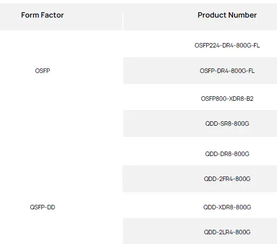
Form Factor and Product Number
| Form Factor | Product Number |
|
OSFP |
|

References
- [1][2][3] Cisco Optical Transceiver Handling Guide ( https://www.cisco.com/c/dam/en/us/td/docs/interfaces_modules/transceiver_modules/installation/guide/optical-transceiver-handling-guide.pdf )
- [4] MMS4X00-NM 800Gbps Twin-port OSFP 2x400Gb/s InfiniBand and Ethernet Single Mode DR8 500m ( https://docs.nvidia.com/networking/display/mms4x00nm800g500m/specifications)
- [5] Removing and Installing Transceivers and Fiber-Optic Cables ( https://www.juniper.net/documentation/us/en/hardware/mx10008/topics/topic-map/mx10008-replace-tranceivers.html)
FAQ
Q: What precautions should be taken when handling the transceiver module?
A: When handling the transceiver module, follow these precautions:
- Avoid moisture exposure.
- Do not disassemble or modify the module.
- Wear anti-static gloves to prevent ESD damage.
- Avoid direct viewing of the fiber optic port to protect your eyes.
- Only allow qualified personnel to perform installation or replacement.
Q: Why is monitoring operating temperature important for the transceiver module?
A: Monitoring the operating temperature is crucial because:
- High temperatures can lead to signal attenuation and degraded transmission quality.
- Elevated temperatures accelerate component aging, reducing the module’s lifespan.
- Risk of failure increases at excessive temperatures, potentially causing permanent damage.
Documents / Resources
 |
FS 800G OSFP Transceiver Module [pdf] Instruction Manual OSFP, QSFP-DD, 800G OSFP Transceiver Module, 800G OSFP, Transceiver Module, Module |