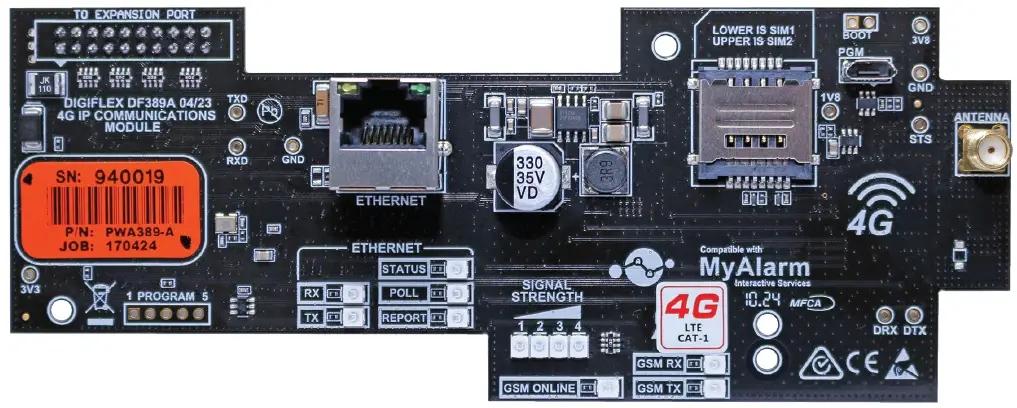
BOSCH CM371B IP Combo Module
Product Information
- Product Name: CM371B IP Combo Module – 4G LTE CAT 1
- Category: Security Systems
- Network: 4G LTE CAT 1
- Communication: IP
- Compatibility: Solution 6000 Series, Solution 6000-IP Series 3.00.67
Product Usage Instructions
- Step 1 – Installing the Radio Module:
- Power off the panel before proceeding.
- Plug the plastic standoffs into the module and then plug it into the Expansion Port header pins on the panel.
- Install the SIM card into the SIM 1 card position.
- Step 2 – Installing the Antenna:
- Remove the knockout at the top of the cabinet.
- Pass the antenna lead through the hole ensuring the antenna is on the outside of the cabinet.
- Screw the lead to the socket on the radio module before powering the panel.
- Step 3 – Configuring The Module:
Connect the Ethernet port to the customer’s network using the supplied cable or other suitable cable. - Step 4 – Configuring The Module:
Once powered, the radio will attempt to connect to the network. Position the antenna for optimal signal strength. - Step 5 – Configuring The Panel Reporting:
Configure reporting formats in MENU 5-4-0 and 5-4-1 to report to the base station in Conettix IP, SIA IP, CSV, or to selected phone numbers via SMS.
Frequently Asked Questions (FAQ):
- Q: What should I do if the online indicator on the module does not start flashing after powering on?
A: Check the SIM card and network connection, ensure proper installation of the antenna, and verify the power supply to the panel. - Q: Can I use any SIM card with data allowance for this module?
A: Yes, ensure that the SIM card is compatible with the carrier network and has an adequate data plan for reliable performance.
Introduction
- The CM371B 4G CAT-1 IP Communication Module allows you to interface compatible security control panels to the cellular data network providing a high-reliability reporting path. The module includes a wired Ethernet port providing a dual path reporting solution.
- The CAT 1 network is widely supported by all carriers however if the unit is being installed in a remote location, you should ensure the carrier you are using has sufficient coverage (signal) for reliable performance. SIMs must be on a plan that includes a data allowance.
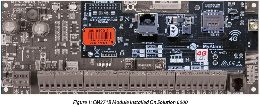
- The unit is installed onto the main control panel using the supplied plastic standoffs, while the supplied antenna should be mounted onto the outside of the metal cabinet.
| Module Compatibility | |
| Panels Supported | Version |
| Solution 6000 Series | 2.53.67 |
| Solution 6000-IP Series | 3.00.67 |
Table 1: Module Compatibility
Getting Started
There are four main steps required to configure the CM371B for reporting to the control room. The instruc-tions assume that you already have purchased a SIM card and that the card has been charged with credit and acti-vated on the network if necessary.
- Install the SIM card into the lower card socket. (SIM1)
- Install the CM371B hardware on the control panel.
- Install the antenna.
- Configure the module’s features and parameters.
- Configure the control panel for reporting.
- Step 1 – Installing the Radio Module
- Ensure that the panel is powered off before proceeding. Plug the 2 short plastic standoffs into the module and then plug them into the Expansion Port header pins on the panel as shown.
- Install the SIM card into the SIM 1 card position.
- Step 2 – Installing the Antenna
- Remove the knockout in the top of the cabinet and pass the antenna lead through the hole ensuring the antenna is on the outside of the cabinet. Screw the lead to the socket on the radio module before powering the panel.
- Do not fix the antenna in place at this stage.
- Step 3 – Configuring The Module
Connect the Ethernet port to the customer’s network using the cable supplied or other suitable cable. - Step 4 – Configuring The Module
- Once powered the radio will attempt to connect to the network. This may take up to a minute to complete. Dur-ing this time the online indicator on the module will be on solid. Once the radio has registered the online indicator will begin to flash and the signal strength indicators will show the current signal condition.
- Experiment with the position of the antenna to find the best signal strength before fixing it in place.
- Step 5 – Configuring The Panel Reporting
- Reporting configuration will vary depending on the required options and whether or not the GSM module is to be used as the primary or secondary reporting route.
- Configure the required reporting formats in MENU 5-4-0 and 5-4-1. The system can be configured to report to the base station in Conettix IP, SIA IP, CSV or to selected phone numbers via SMS.
All reporting scenarios are configured by varying the programming of the reporting format and reporting routes configuration options.
Module Indicators
The module includes a total of 12 LED indicators which are used to show status and signal strength information. Separate indicators are provided for the GSM and Ether-net systems. Additional feedback is provided through the keypad and via the interactive option in Solution Link. See the tables below.
| Module Indicators | |
| Indicator | Meaning |
| TX | Module Transmitting Data |
| RX | Module Receiving Data |
| Online | ON Steady = Not Registered On Network Pulsing = Registered On Network |
| Signal 1 | Signal strength indicators show the relative signal level at the radio. Signal indicator 1 indicates a weak signal and all 4 indicators indicate stronger signal strength. |
| Signal 2 | |
| Signal 3 | |
| Signal 4 | |
Table 2: GSM/GPRS Indicator Meanings
| Ethernet Indicators | |
| Indicator | Meaning |
| TX | Transmitting Data via Ethernet |
| RX | Receiving Data via Ethernet |
|
STATUS |
ON = Trouble – No Communication between Panel and Module.
Slow Flash = Normal Operation Fast Flash = No IP Address or IP Address Conflict – See System Troubles |
| POLL | Flashes every time the control panel sends a poll packet. |
| REPORT | Flashes each time the control panel sends an alarm report. |
Table 3: Ethernet Indicator Meanings
| RJ45 Socket Indicators | |
| Green LED | Meaning |
| OFF | No Link / Connection |
| ON | Link Present |
| Blinking | Link with TX / RX Activity |
| Amber LED | Meaning |
| OFF | Half Duplex Activity |
| ON | Full Duplex Activity / Off |
| Blinking | Collision Activity |
Table 4: RJ45 Socket Indicator Meanings
Supported Reporting Formats
The following reporting formats are currently supported by the module.
- SMS Format via GSM
- CSV-IP Format via GPRS
- Conettix Format via GPRS
- CSV-IP Format via Ethernet
- Conettix Format via Ethernet
- SIA Format via Ethernet
There is no support for Contact ID (CID) over GSM.
Note
The Solution 6000-IP control panel does not support SMS Format via GSM.
CLI Trigger Output Control
- The CLI trigger tables in MENU 6-5-5-0 and 6-5-6-1 can be used to store a list of telephone numbers that can trigger output on the control panel. If you call the GSM unit from a telephone number that matches a number in the CLI list then the appropriate output will be operated.
- Output needs to be programmed with an event type of CLI Trigger and event assignment of 1 or 2 depending on which table is to be checked.
- Simply call the GSM unit from a telephone number that is programmed in the CLI trigger list to activate the output.
Note
The Solution 6000-IP control panel does not support CLI Trigger Output Control.
Module Status
MENU 6-5-0 can be used to obtain various information on the radio module. The following information is currently available.
- Connected Network
- Signal Strength in dB
- IMEI Number
- Radio Firmware Revision
- SIM Card Present
SMS Remote Control
- The SMS control option in MENU 6-5-6 allows you to program up to 10 telephone numbers that are allowed to send SMS commands to the GSM unit.
- Numerous commands can be sent to the panel using the SMS control functions including arming/ disarming areas, controlling outputs and doors or checking system status. The panel can also be requested to send a confirmation SMS if required. The control messages must be sent to the SIM phone number.
- The SMS Control phrase table shows the correct method for constructing the SMS messages. Note there are no spaces between the fields only commas as shown.
Note
The Solution 6000-IP control panel does not support SMS remote control or the SMS Control Smartphone App detailed below.
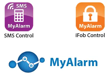
SMS Control Smartphone App
The MyAlarm SMS Control App for iOS and Android devices is now available and can be used to simplify the configuration and sending of SMS control messages.

You can search for the MyAlarm SMS Control app in the app store or scan the QR codes below using your device’s barcode reader for a direct link to the app.


Smart Device Apps
Smart device apps are available to enhance alarm reporting and provide real-time control of system areas, outputs, doors, etc. More information can be found in the app stores or on the MyAlarm website at www.myalarm.com.au.
SIM Balance Recharge Reminder Function
Note
The SIM Balance feature of the SMS Control App is no longer supported due to network provider changes.
Using
GPRS Using The CM371B 4G Radio
The APN Server Name, APN User Name, and APN Password menus need to be configured before the 4G radio can establish a GPRS or data connection with the telco provider. Applications such as the MyAlarm iFob control app or reporting back to base over the GPRS connection require the data connection.
- Devices > GSM/GPRS Module >
APN Server Name
MENU 6-5-7
APN (Access Point Name)
Enter the appropriate name of your GPRS mobile network provider to connect to the public Internet. For example
- Telstra APN=telstra.wap
- Optus APN=yesinternet
- Vodafone APN=live.vodafone.com

- Devices > GSM/GPRS Module >
APN Username
- MENU 6-5-8
This can be used to identify you on a network however is mostly left BLANK.

Devices > GSM/GPRS Module >
APN Password
- MENU 6-5-9
A secret word or phrase that must be used to gain admission to the network however mostly left BLANK.

|
Description |
SMS String |
| Arming / Disarming Areas | |
| Turning Area 1 On | <User Code>, AREA,1, ON |
| Turning Area 1 On With Confirmation | <User Code>, AREA,1, ON, CONFIRM |
| Turning Area 1 Part 1 On | <User Code>, AREA, 1, PART 1 |
| Turning Area 1 Part 1 On With Confirmation | <User Code>, AREA,1, PART 1, CONFIRM |
| Turning Area 1 Part 2 On | <User Code>, AREA,1, PART 2 |
| Turning Area 1 Part 2 On With Confirmation | <User Code>, AREA,1, PART 2, CONFIRM |
| Turn Multiple Areas On | <User Code>,AREA,1,2,3,4,ON |
| Turn All Areas That the User Belongs To | <User Code>,AREA,ON |
| Turning Area 1 OFF | <User Code>, AREA,1, OFF |
| Turning Area 1 OFF With Confirmation | <User Code>, AREA,1, OFF, CONFIRM |
| Check Area Status | <User Code>, AREA,1, STATUS |
| Check the Status Of Multiple Areas | <User Code>,AREA,1,2,3,STATUS |
| Turning Outputs On/Off | |
| Turn Output 1 On | <User Code>, OUTPUT,1, ON |
| Turn Output 1 On With Confirmation | <User Code>, OUTPUT,1, ON, CONFIRM |
| Turn Multiple Outputs On | <User Code>,OUTPUT,1,2,3,4,ON |
| Turn Multiple Outputs On With Confirmation | <User Code>,OUTPUT,1,2,3,4,ON,CONFIRM |
| Turning Output 1 OFF | <User Code>, OUTPUT,1, OFF |
| Turning Output 1 OFF With Confirmation | <User Code>, OUTPUT,1, OFF, CONFIRM |
| Turning Multiple Outputs OFF | <User Code>,OUTPUT,1,2,3,4,OFF |
| Turning Multiple Outputs OFF With Confirmation | <User Code>,OUTPUT,1,2,3,4,OFF,CONFIRM |
| Check Output Status | <User Code>, OUTPUT,1, STATUS |
| Check the Status Of Multiple Outputs | <User Code>,OUTPUT,1,2,3,4,STATUS |
| Locking and Unlocking Doors | |
| Unlock Door 1 | <User Code>, DOOR,1, UNLOCK |
| Unlock Door 1 With Confirmation | <User Code>, DOOR,1, UNLOCK, CONFIRM |
| Unlock Multiple Doors | <User Code>,DOOR,1,2,3,UNLOCK |
| Unlock Multiple Doors With Confirmation | <User Code>,DOOR,1,2,3,UNLOCK,CONFIRM |
| Lock Door 1 | <User Code>, DOOR,1, LOCK |
| Lock Door 1 With Confirmation | <User Code>, DOOR,1, LOCK, CONFIRM |
| Lock Multiple Doors | <User Code>,DOOR,1,2,3,LOCK |
| Lock Multiple Doors With Confirmation | <User Code>,DOOR,1,2,3,LOCK,CONFIRM |
| Check the Status Of A Door | <User Code>, DOOR,1, STATUS |
| Check the Status Of Multiple Doors | <User Code>,DOOR,1,2,3,STATUS |
| Check System Status | <User Code>,SYSTEM,STATUS |
Table 5: GSM SMS String Commands
Ethernet Port Setup
The Ethernet port on the CM371B IP Communication Module – 4G allows you to interface compatible security control panels to the building’s hard-wired IP connection point using a CAT 5E connection cable. Once configured and operating you will be able to report to monitoring centers that support the available IP reporting formats and to upload/download to the control panel through an internet or intranet connection.
Step 1 – Getting Started
- A number of IP connection tools are included in the Solution Link RAS software and it is recommended that you make use of these when configuring the CM371B. At this point, you should connect your laptop to the same LAN that the CM371B is connected to and then run Solution Link.
- If the premises has a Network Administrator you should work with them to complete the installation as a number of steps listed below can be avoided if the administrator can provide you with the required information.
Note
It is important at this point to record the MAC or physical address of the CM371B IP module for future reference. You can record this information in the “Customer Details”.
Ensure that the panel is powered off before proceeding. Plug the 2 short plastic standoffs into the module and then plug them onto the Expansion Port header pins on the panel as shown in “Figure 1: CM371B Module Installed On Solution 6000” on page 2. Once the cable is connected and the panel is powered, observe the module’s green Status LED. Under normal operation, the Status LED will remain steady for approximately 3 seconds following power-up while the system configures the module. During this process, if the connected internal network is DHCP enabled, the module will request an IP address from the DHCP server. Once the module receives an address the Status LED will begin to flash slowly.
If the Status LED is flashing fast then the module has not received an IP address or there is a IP address conflict. If this occurs check all LAN wiring to the module and or contact the network administrator for assistance.
Step 2 – Configuring the IP Module’s Network Settings
- The CM371B module will need a fixed or reserved IP address on the network that it is to be connected to. If the network administrator is available then they should provide you with the Default Gateway, Subnet Mask and IP Address to be used.
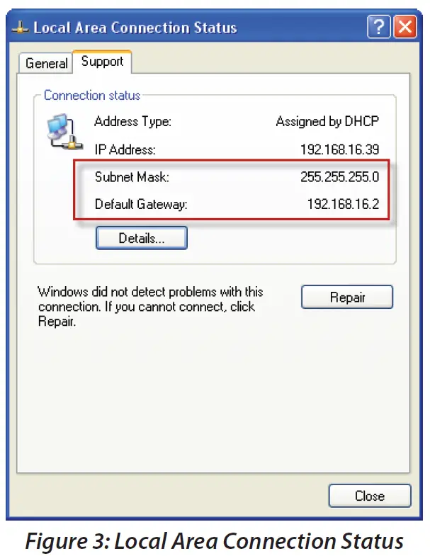
- If you are trying to determine this information without an administrator then you will need to obtain the Default Gateway and Subnet mask for the network. To do this run the IPCONFIG command on your laptop or another PC that is connected to the same network as the module.
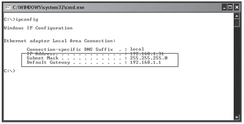
- IPCONFIG will list the Default Gateway, and Subnet Mask as well as the IP address of the PC that executed the command. Note this is not the IP address assigned to the CM371B and is not needed to complete the installation.
- You can also access this information by running Control Panel, and Network Connections, and then double click on Local Area Connection and select the support tab.
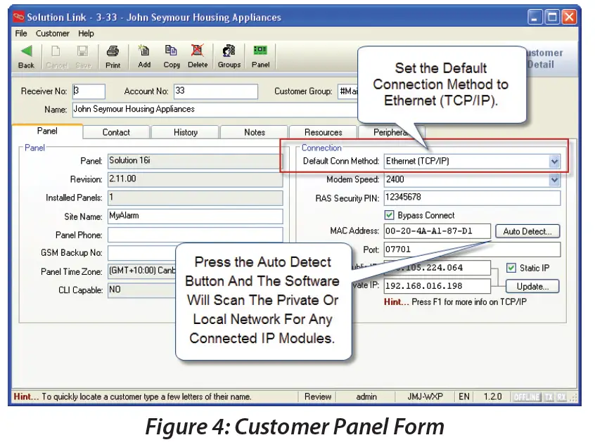
- Once you have this information, create a new customer record in Solution Link or open an existing one if you are adding the CM371B module to an existing customer. From the Customer Panel form, set the default connection method to Ethernet (TCP/IP) and then press the Auto Detect button to launch the Network Assistant.
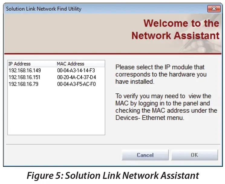
- Press the OK button and the assistant will begin scanning the private network LAN for the presence of CM371B modules. If more than one module is found, select the one from the list whose MAC address matches the one you are installing and press the [OK] button.
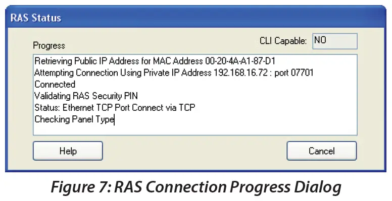
- You should now be able to establish an RAS session with the panel over the local or internal network connection. This will only be possible provided that the laptop or PC running Solution Link is on the same network as the CM371B module.
- Click the panel button on the toolbar followed by the connect button and then select Ethernet to start the con-nection.

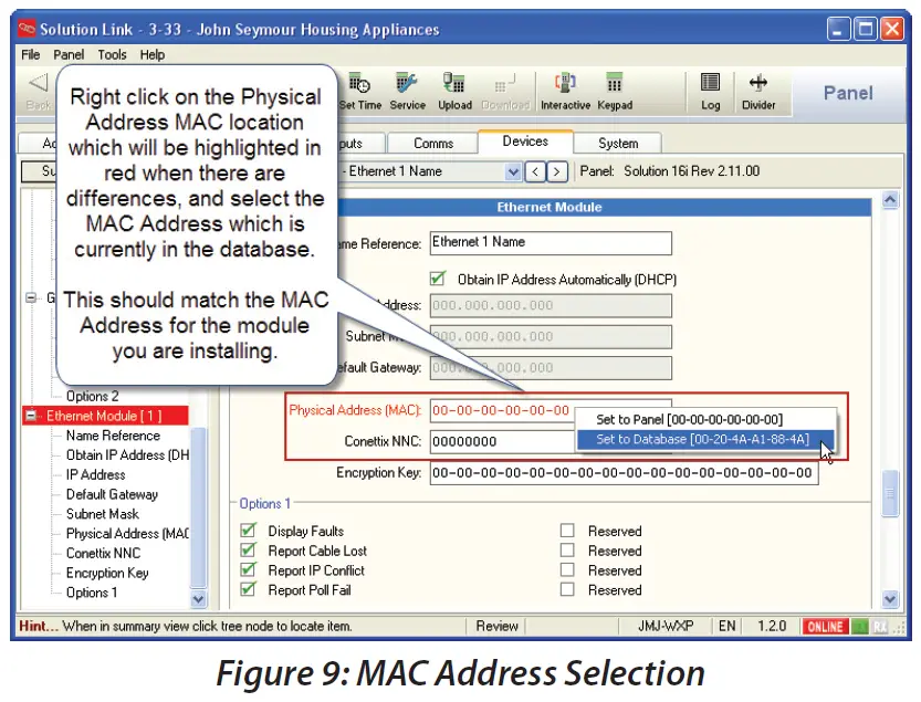
- Once connected, upload the panel data. Solution Link will compare the panel data with the data in the database and will then display a list of differences similar to those shown in “Figure 8: Uploaded Differences”.

- Move to the Devices tab and select Detail View, then scroll down or use the navigation tree to locate the Ethernet Module section. Right-click on the Physical Address (MAC) field and select the MAC address that is in the database. This should match the MAC Address of the module you are installing.
- Review any other highlighted differences and then save the changes to the database.
- Go to the Ethernet Module section in the Devices tab and uncheck the “Obtain IP Address Automatically” option then enter the IP Address of the CM371B, the Subnet Mask, and the Default Gateway in the fields provided and then save the changes.

Step 3 – Configuring the Panel for IP Reporting
Before you will be able to configure the panel for IP reporting you will need to make sure you have the relevant information from the control room. The following is required.
- IP Address for the base station’s IP Receiver.
- IP Port for the base station’s IP Receiver.
- Poll Rate.
- Acknowledge Wait Time.
- Reporting Format.
- If Conettix NNC Anti Replay format is being used, you will need the base station allocated NNC Number.
- If encryption is required you will need the base station allocated Encryption Key.
Move to the Reporting Route section on the Comms tab and set the transmission format to Ethernet format for Destination 1, 2 or both as required.

Move to the IP Reporting section on the Comms tab and enter the Base Station Receiver IP Address, IP Port, and other parameters as supplied by the control room. Enter the details in the appropriate destination as required.

If you are using the Conettix NNC anti-replay feature or data encryption move to the Ethernet Module section on the Devices tab and enter the respective information. The values entered here must match those in the base station or communication will fail. To remove encryption set the key back to all zeros or the factory default settings.

Step 4 – Configuring IP Remote Access
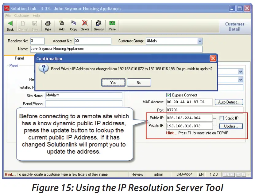
- When attempting a remote connection to a site that has a CM371B module fitted the site’s public IP address will be required. In many cases, the site’s public IP address is dynamically allocated by the ISP and therefore it can change at any time.
- To cater for this situation the CM371B module will send a periodic message to a proprietary central IP Resolution Server (IPRS) which maintains a record of the site’s current public IP Address. When you attempt the remote con-nection using Solution Link the software will provide you with the customer’s current public IP address.

IP Remote Access
If required you can configure the module to only accept incoming connections from a specific IP Address. In the default state, the RAS IP Address is set to 000.000.000.000 for both users and installers and this allows a connection to the panel from any IP Address. To limit access so that an RAS connection can only be established from only one IP address enter it here.
- This option should be used with caution and should only be used if you have a static public IP address and you only want/need to connect to the panel from one location.
- If a UDP connection is necessary for remote access then you will also need to program this option. See “UDP Protocol Options” on page 11 for more information.
- The RAS IP port is defaulted to port 07701 for both users and installers. This must be programmed the same in the panel and Solution Link RAS software.
- You will need to create a port forwarding rule on the customer router to direct incoming traffic on this port to the CM371B module’s private IP Address.
Note
If you attempt an IP connection with an incorrect RAS security PIN then after 6 attempts to panel will lockout for the IP RAS lockout time period programmed in MENU 5-7-3.
Port Forwarding and IP Address Reservation
- This is by far the most likely place where errors can be made due to the fact that there are so many different routers in the marketplace.
- Essentially to gain access remotely to the CM371B for an upload/download session the client’s router will require a rule to be created that opens and directs all IP traffic coming into the router for port 07701 (default IP RAS Port) to the internal IP address of the CM371B which is pro-grammed in MENU 6-6-0 on the Solution 6000.

You will also need to make sure that the DHCP server is configured to reserve or lock down the IP Address that was assigned to the CM371B module when it was first connected to the LAN. See the Module IP Address location which is MENU 6-6-0 on the Solution 6000 panel.
Note
If the port forwarding is not correctly setup then you will not be able to connect to the panel remotely via IP.
UDP Protocol Options
- Before connecting to a remote panel the installer needs to decide between one of two internet protocols UDP or TCP. UDP (User Datagram Protocol) is a connectionless protocol.
- The packets of exchanged data are smaller and with less overhead however, the IP network does not guarantee receipt. Although UDP is connectionless, the RAS software application confirms delivery of each packet so although the layer does not guarantee delivery, the application does so there should be no concerns using UDP as a trans-port method. TCP (Transmission Control Protocol) is one of the main protocols in IP networks. TCP establishes a full connection to exchange streams of data between two points and the network guarantees delivery.
- Which protocol should you use? If you are able to allocate and open more than a single port at an installation or If you intend to remotely connect to sites using multiple PCs that are part of an office network or behind a firewall then you would be best served by selecting TCP as your preferred connection method.
- If however, you are at a site that will only allow you to open a single port and your reporting format is TCP-based like the CSV IP format, then you have no choice but to select UDP for RAS connections. UDP transactions are faster but depending on your network you may need to marshal packets (port forward) to the PC running Solution Link RAS software. By default, the CM371B is configured for Remote Access using UDP/IP protocol.

Optional AN110 High Gain Outdoor Antenna
- For installations where adequate signal strength is not available using the supplied indoor antenna, an optional outdoor antenna can be used.
- The AN110 antenna offers up to 10dBi peak gain (4G) and is supplied with a mounting bracket, mast U clamp, and a 15m RG58 cable with N-male to SMA-male connectors.
Specifications
| AN110 Specifications | |
| Frequency Range | 698~960Mhz/1710~2700Mhz |
| Impedance | 50 Ohms |
| VSWR | <1.5 |
| Gain | 10dBi Peak |
| Polarization | Vertical |
| Radiation | Omni Directional |
| Color | White |
| Operating Temp | -40 ~ +60 Celcius |
| Size | 246mm x 75mm x 82mm |
Table 6: AN110 Specifications

Customer Details
Use this section to record the customer details for this CM371B module. This information may also be required when seeking technical support.

Feature Differences Between Panel Types
The following table highlights the feature differences when using this module with different panel types.
|
Feature |
Solution 6000 |
Solution 6000-IP |
| SMS Reporting via GSM | Yes | No |
| CLI Trigger Output Control | No | No |
| SMS Remote Control | Yes | No |
| SIM Balance Reminder Feature | No | No |
Table 7: Feature Differences Between Panel Types
Specifications
- Part Number: CM371B – IP Combo Module – 4G LTE CAT 1 with Ethernet
- Operating Voltage: Supplied by Panel – Derate the maximum available 12V accessory power from the panel by 100m when the module is fitted.
- Compatible With: Solution 6000 (Firmware V2.53.67) Solution 6000-IP (Firmware V3.00.67)
- Network Interface: RJ45 Ethernet 10BASE-T or 100BASE-T (Auto Sensing)
- Encryption: 128-bit AES
- Reporting Formats: SMS via GSM on selected panels
- CSV-IP, Conettix, SIA IP, and MyAlarm formats are supported via GPRS and Ethernet iFob Control app, and SolutionLink RAS connections are supported.
- The CM371B does not support Contact ID (CID) over GSM.
- Radio: 4G Quectel EG800Q-EU – CAT-1 Network
- SIM Card Type: Standard full-size SIM card. The SIM card should be installed in the SIM 1 socket.
- Antenna: Quad Band Omni Directional with Magnetic Mount, integrated lead, and SMA Connector. 3dbi gain – 50 ohm
- Module Connection: The CM371B is mounted directly to the expansion port on the control panel PCB. Two plastic standoffs are supplied to support the module and these should be connected to the control panel before installing the CM371B.
- Operating Environment: 0˚ to 55˚C RH 5 to 85% at 30˚C non-condensing.
- Warranty: 3 years from date of manufacture (return to base)
In the interest of ongoing product development, this document is subject to change without notice.
Bosch Security Systems
- Level 2, 21 Solent Circuit Baulkham Hills, NSW 2153 Australia
- Phone: 1300 026 724
- www.boschsecurity.com.au.
© 2024 Bosch Security Systems
Documents / Resources
 |
BOSCH CM371B IP Combo Module [pdf] User Guide CM371B, CM371B IP Combo Module, IP Combo Module, Combo Module, Module |


